The technical team at Schaeffler Automotive Aftermarket takes CVW through a full clutch replacement on a VW Caddy 1.6 TDI.
In this month’s article, we are replacing the clutch on a 2011 Volkswagen Caddy fitted with a 1.6 TDI common rail CAYD engine. The suggested problem was that the clutch slips under load and a short road test confirmed that to be the case and with a mileage of more than 92,000, clutch replacement was advised.
Volkswagen introduced the Caddy to Europe in 1982, with the current model being the third generation. It is available in two body sizes and with many variants. This model Caddy is based on a Volkswagen Touran with Volkswagen Golf Mk 5 front suspension, and was named best small van of the year in 2007 and 2008. The Volkswagen Caddy shares the same platform as other VAG models with a transverse engine/gearbox arrangement, so there is a good chance this will look quite familiar when the bonnet is raised.
We used the following equipment for this repair: a scissor lift, transmission jack and an engine brace. If the vehicle is equipped with locking wheel bolts, locate the locking wheel bolt key before commencing the repair.
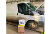
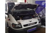
With the vehicle positioned on the ramp, open the bonnet and remove the engine cover, air intake duct and air filter assembly, disconnect the battery and remove the battery followed by the battery carrier. This now exposes the top of the gearbox, giving us good access for component removal (Fig 1).
Disconnect the gear change cables from the selector linkage, remove the three bolts from the gear cable support bracket and stow in the bulkhead area. Remove the plastic quadrant (Fig 2) from the selector mechanism by removing the retaining clip. This will ensure the quadrant is not damaged during the gearbox removal and installation. Take off the centre nut from the selector mechanism and remove the gear change weight. Now remove the clutch slave cylinder assembly, inspect the slave cylinder for any fluid leaks or wear to contact areas. We found wear on the end of the slave cylinder push rod (Fig 3), so a clutch slave cylinder replacement was advised.

Disconnect the earth cable from the bell housing bolt, followed by the reverse light switch wiring multiplug and then the wiring from the starter motor. At this point the top starter motor bolt and top bell housing bolts can be removed.
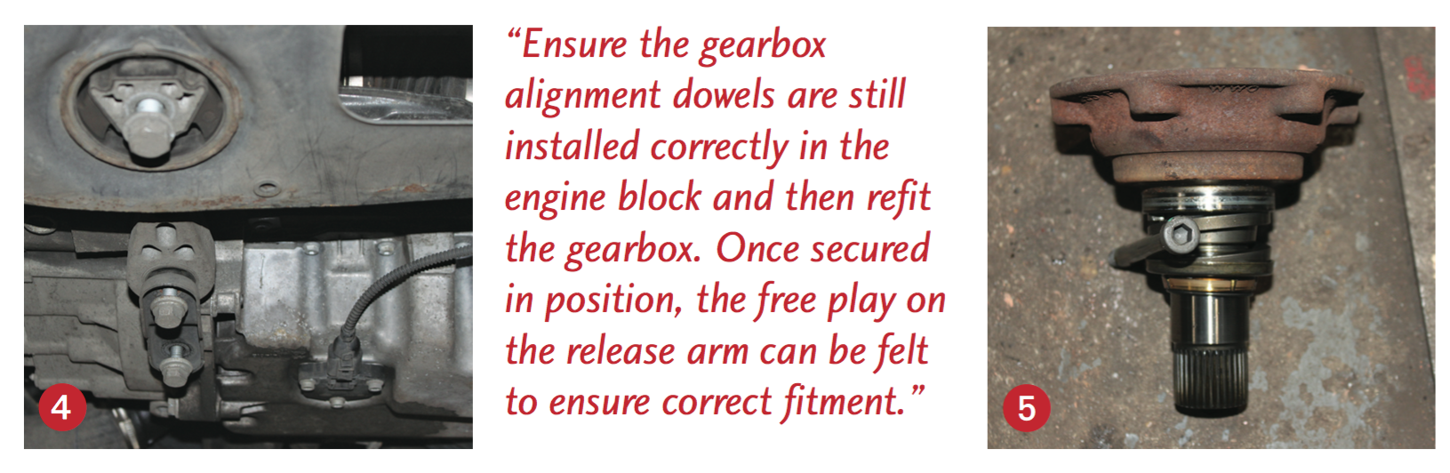
Slacken both front wheel locking bolts with a bar and then raise the ramp to waist height, remove both front wheels and the N/S/F wheel arch liner, then raise the ramp to access the underside and remove the engine under tray. Remove the gearbox pendulum mounting (Fig 4), and take out the six driveshaft flange retaining bolts from both driveshafts, disconnect the ball
joints from the bottom suspension arms and release. There will now be enough clearance to move and secure the driveshafts away from the gearbox to aid gearbox removal. The O/S gearbox output flange can now be removed by taking out the centre bolt. Be careful when removing the flange as some gearbox oil can run out (Fig 5).
Now remove the bottom bell housing bolts, bottom starter motor bolt and the starter motor, lower the ramp and support the engine with an engine beam or support frame. Release the gearbox mounting and then lower the engine on a beam to a position where the gearbox can be removed. Raise the vehicle and support the gearbox with a transmission jack, so that the gearbox mounting bracket bolts can be accessed from the N/S/F wheel arch area. Remove the three bolts and the bracket (Fig 6), then take out the final bell housing bolts and remove the gearbox with the aid of the transmission jack.
With the gearbox out of the way, the clutch was removed and, as diagnosed, it had reached the end of its service life. The solid flywheel was inspected and confirmed to be okay and the ‘glaze’ was removed from the flywheel face using emery cloth. The flywheel and back plate area should be cleaned to remove the old clutch dust. Remove the clutch release arm, bearing and gearbox input shaft sleeve and clean the clutch dust out of the bell housing area. Lubricate the gearbox input shaft splines with high melting point grease and then slide the new clutch plate onto the input shaft to confirm the splines are correct and to dissipate the grease evenly, then wipe off any excess.
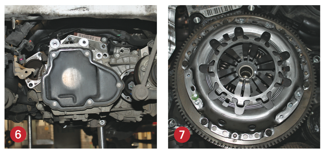
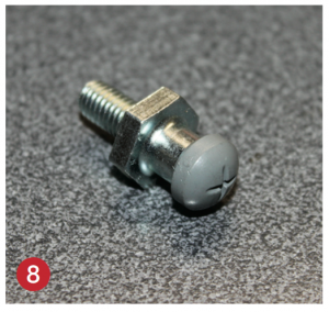
Now fit the new clutch assembly (Fig 7) using a clutch alignment tool. Always inspect the release arm and pivot points. On our Caddy, we noticed some wear to the pivot point, so this was replaced (Fig 8) along with the release arm that is provided in the clutch kit. Fit the new input shaft sleeve, clip the new release bearing into the release arm, apply a small amount of high melting point grease to the pivot points and then fit the release arm and bearing, securing the pivot point with the retaining clip.
Ensure the gearbox alignment dowels are still installed correctly in the engine block and then refit the gearbox. Once secured in position, the free play on the release arm can be felt to ensure correct fitment before full installation is carried out in reverse order of removal. A new clutch slave cylinder was fitted at this point and the clutch hydraulic system was gravity bled, with torque bolts returned to the manufacturer’s specifications. Check and top up the gearbox oil level as required. Ensure all electrical items are reset after the battery has been connected, and finally, carry out a full road test to ensure clutch and gearbox operation are correct.