Using an oscilloscope to solve intermittent fault
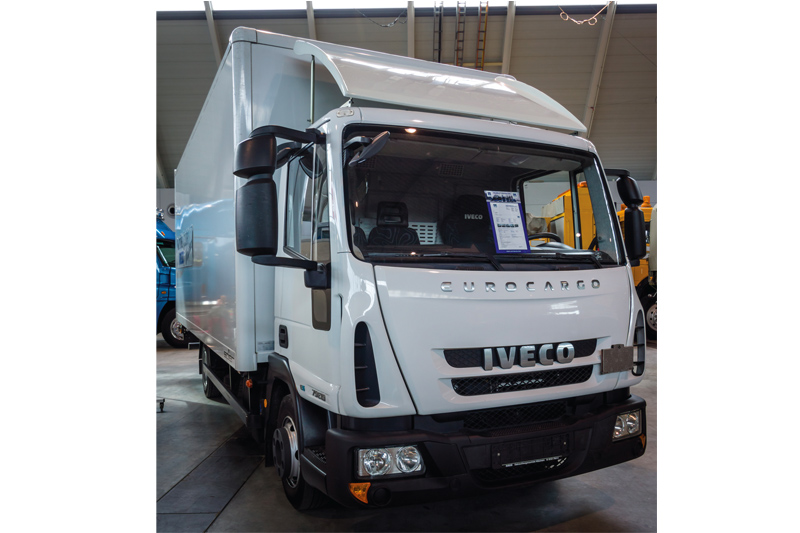
An annoying intermittent fault on an Iveco Eurocargo comes under the oscilloscope. Ben Martins of Pico Technology tells the story.
No-one likes an intermittent fault. You can guarantee that by the time you get to look at it, the problem won’t be there and the chances of it reappearing will be once you hand the vehicle back to the customer. I was asked to join a customer following precisely this situation where an initial assessment was carried out only for the intermittent fault to not reappear during the diagnosis. Only once the driver was back on the road did it come back and when this fault occurred, the gearbox would select neutral, idle speed would increase, there was a lack of throttle response and then the vehicle would just sit there with no way of moving it.
CAN do approach
With the warning lights on the dashboard the first step was to take a look at the fault codes. A large number of codes presented with the active faults being in the gearbox stating missing messages and CAN message errors. The majority of the faults were pointing towards the CAN network. With everything saved, all fault codes were deleted in order to see if any were returned and, as expected with an intermittent fault, all cleared with no faults present.
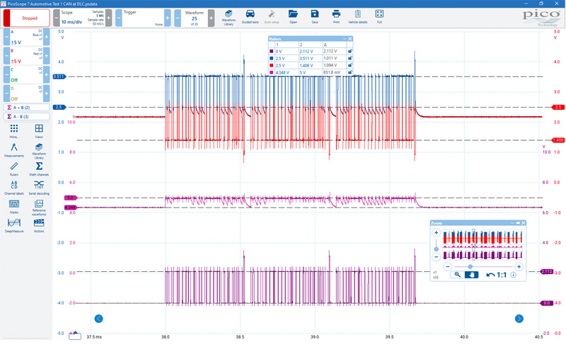
Grabbing the scope we took a look at the network at the 16-pin DLC connector. There is also a 32-pin connector with some Ivecos but the 16-pin was the connector used to obtain the fault codes.
The raw signals from CAN H and CAN L were taken referenced to chassis ground and the maths channels A+B and A-B were added. Even without the maths channels something wasn’t right. Using the signal rulers we saw that when the bus was inactive, the idle voltage was sitting just over 2V when we should be expecting 2.5V. This was also highlighted in the A+B maths channel which should be a relatively flat line at 5V. When a message was broadcast, the voltage did jump up to 5V which is expected. CAN H at 3.5V and CAN L at 1.5V when added together give you 5V.
By including A-B we got to see what the ECU is seeing as internally this is what is happening. A differential network like CAN is especially fault tolerant as by subtracting the two, any interference which is present in both CAN H and CAN L is removed leaving a much cleaner signal to carry out decoding on. This is why the A-B signal looked pretty much perfect as we had 0 – 2V which was expected. Despite the voltage levels not being correct, as far as the ECU was concerned it could still decode the messages being sent without any issues. Considering we had missing messages and CAN errors something more major was happening.
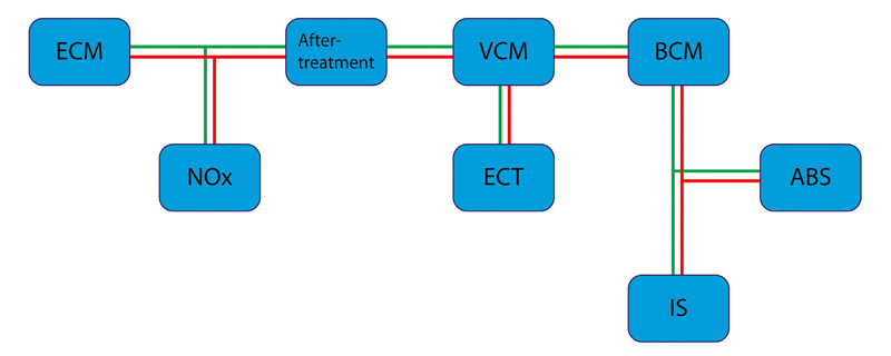
Being as the problem was intermittent sometimes you can manifest the issue by attempting to recreate the symptoms. Going from the fault codes the engine ECU was reporting missing messages between the gearbox ECU and the same went for the gearbox ECU reporting missing messages from the engine ECU. Using the wiring diagram we redrew the CAN network.
Network down
Given its location in the network and on the vehicle, we disconnected the aftertreatment ECU with the engine running leaving just the ECM, NOx sensor and aftertreatment ECU in the network. As expected the dash illuminated with all the warnings and the engine idle speed increased as well which was the same as when the fault occurs.
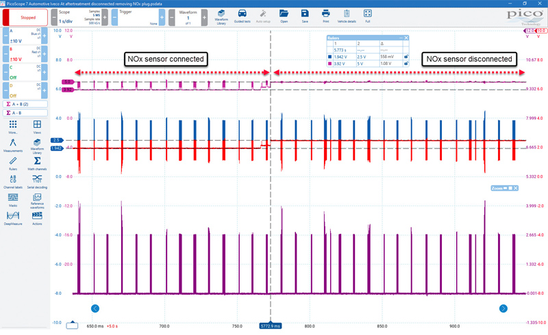
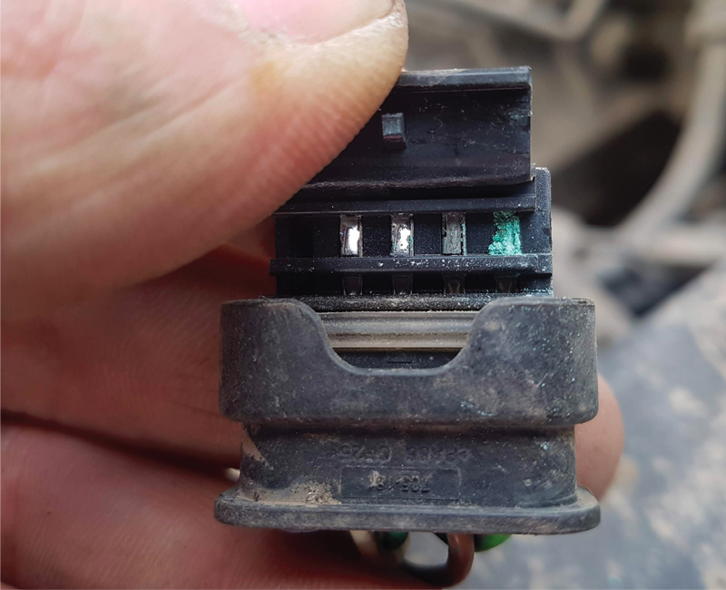
With the scope connected to the CAN on the aftertreatment ECU we could still see that the idle voltage was not right. Moving to the disconnected side of the network the voltage levels were correct pointing us towards an issue within the aftertreatment ECU, engine ECU or the NOx sensor. Based on location the NOx was disconnected and we saw the network voltage restored. But as we could see the ECUs would still have no issue decoding despite this voltage problem so what could be causing the issue where the network seemingly shuts down? With the NOx sensor disconnected a visual inspection was carried out where we found a build up of corrosion on one of the terminals indicating water ingress.

Clearly that wasn’t right and needed correcting and if water ingress was getting into the connector was an internal malfunction causing further problems, like a short across CAN H and CAN L? There was only one way to find out and that was to manually cause a short.
Mystery ‘modification’
Reconnecting the aftertreatment ECU to the rest of the network but leaving the NOx disconnected, we saw that our BUS idle voltage was restored to 2.5V and our CAN H + CAN L was at the expected 5V. Shorting the network will of course bring it all down and cause a lot of faults. Interestingly when performing the short, the same symptoms occurred with the engine idle speed increasing, no throttle response and the gearbox moving into neutral.
Seeming the NOx sensor was the likely cause of the issue but something stuck out when deleting the fault codes we had produced. There was no fault code for the NOx sensor being missing. How could that be considering it was disconnected? What was even more intriguing was when we went into the live data, there was data for the NOx sensor which was changing depending on the engine speed! Slightly surprised considering if we only had a scan tool to diagnose with, the NOx sensor would not have been high up on the action list, if it even made it to the list. One possible solution for this situation is if the vehicle had been subjected to a “modification” where the NOx sensor values are recreated in the ECU to make it believe there are no issues with the sensor.
Given the lack of fault codes and the fact the network voltage was restored, the NOx sensor was removed from the network. As this is still an intermittent issue and during the rest of the testing we were unable to recreate the fault, the operator was asked to only use the vehicle within the confines of the building site in order to further test the vehicle to ensure the issue was resolved. Following a number of weeks the issue has not been reported indicating the NOx sensor was indeed at fault. Going forward the customer was advised that to fix the fault a reflash of the ECU to put it back to standard and a new NOx sensor fitted would be required.
Being driven by the data to work towards a diagnosis will give you the evidence required to back up any repair or additional work. This was an interesting fault that was made more difficult due to a deliberate modification to the original system.