How to battery test with an oscilloscope

Everything you need to know about battery testing with an oscilloscope from Pico Technology’s Ben Martins, automotive application specialist.
The humble battery. It’s in everything. With different chemistries, it’s powering everything from your toothbrush to 700T mining machines and everything in between. Ignoring all the fancy lithium batteries, the humble flooded battery is still found at the heart of many vehicles and machines.
As the demand for technology in modern vehicles increases, so does the demand on the low-voltage system. With increases in the number of ECUs, cameras, infotainment systems, OTA updates and more, it’s no wonder that the battery gets a hard time.
Over the years, many different types of battery testing techniques have emerged. Ultimately, however, to test batteries properly, you end up having to destroy them. Not ideal, especially if there was nothing wrong with it to start with, and the customer was in for a winter check!
When it comes to testing batteries on a 24 V system, the traditional testers might only let you test one battery at a time, which takes more time and introduces variability, or combine both batteries for an overall test. With this situation comes the question: Which battery is at fault?
We do know that batteries give up their status most when they are put under load. I remember testing batteries with the old drop testers where, if the bendy bit of metal glowed a nice orange colour it meant the battery was good. Fortunately, technology and common sense prevailed; it’s not like hydrogen and sparks are a bad thing, right?
Modern testers use complex algorithms, pre-existing data comparisons and clever frequency testing to determine a battery’s state of health and charge. In my experience, I’ve seen batteries I know to be bad would sometimes still pass this test, and only when loading the battery would you see it fail. Existing testers, such as carbon pile testers, give much better results off the car, but we could make use of the best test bench we have, the engine itself.

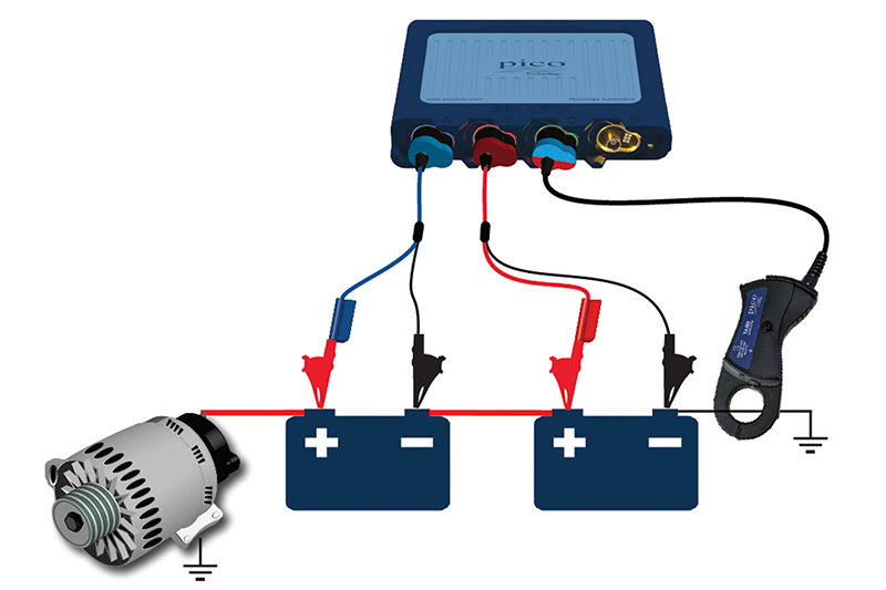
By using the effects that cranking has on a battery, we can start to build a picture of a battery’s health. So, how does an oscilloscope help? Well, the benefit of, say, a 4-channel scope like a PicoScope is that we can now measure both batteries at the same time. In a simple test, you can measure across each individual battery voltage and the overall current that is being drawn from both batteries. Caution – do not try this test if using a common ground scope, especially if you suspect a fault.
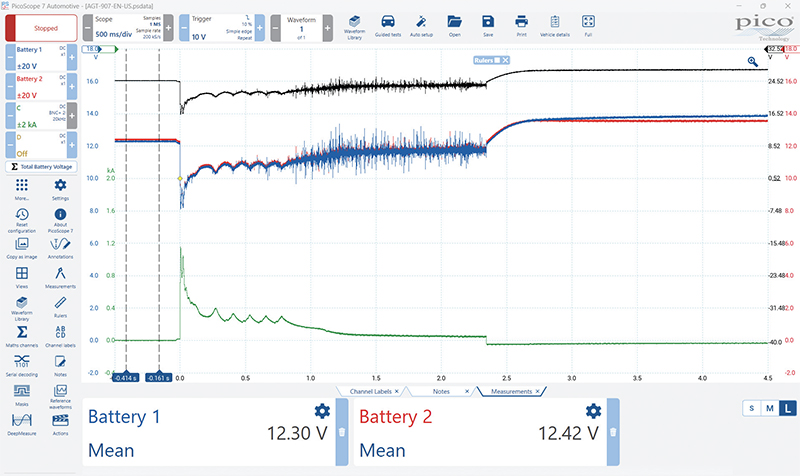
By observing how both battery voltage levels react to cranking, we can get an idea of the battery’s health. In an ideal world, both batteries should be the same. Using the settings file from the guided test, we can make some measurements.
By utilising the time rulers, the mean of the signal between the time rulers can be displayed. On the OCV (open circuit voltage), we see that battery two (red) is slightly higher, indicating that the state of charge is higher than battery one (blue).

Using the zoom tools, we can highlight the point where cranking starts and the batteries are put under the most load. Both batteries drop to pretty much the same, indicating they are contributing equally to the power demand from the starter motor and therefore cranking the engine.
Once the engine has started, the batteries begin to recover, and then, as charging starts, we can see how each battery reacts. In this instance, battery one (blue) seems to be recovering quicker than battery blue. This absorption rate could be an indicator of poor health. In this example, they are still fairly close, so I would be happy that all is OK here and there are no reported issues with starting.
Using a 4-channel scope, though, we still have a channel free. By using the fourth channel, we can include some math channels to show us even more detail, including the voltage drop across the link lead. This test can be performed with common-ground scopes.
In PicoScope 7 automotive software, the guided tests set everything up for you. Let’s talk through the setup. Using the image, the blue channel is connected to the positive of battery one and the negative of battery tw0, so it provides the total voltage for both batteries.
The red channel is connected to the negative terminal of battery one and the ground of battery two, giving the voltage of battery two before the link lead. The green channel is measuring from battery two positive to the negative terminal of battery two, therefore measuring the total voltage of battery two.

Using subtraction, we can calculate the voltage of battery one and the voltage drop across the link lead. For battery one, if we subtract the red channel from the blue channel, we will have the difference between them, and therefore the voltage of battery one. If we then subtract the red voltage from the green channel, we will have the difference between the negative of battery one and the positive of battery two, giving us the voltage drop.
By using the extra channel, you can now see information that you wouldn’t have if using the traditional battery testers. The best part is that it takes around the same amount of time to carry out, and you don’t have to disconnect anything.