Air brake pressure testing
Ben Martins, automotive application specialist at Pico Technology, gets to the bottom of a truck facing problems with its braking, using an unexpected feature of the oscilloscope.
With the introduction of portable USB-based oscilloscopes, what we can do outside the confines of a workshop is now infinitely possible, providing you remember to charge up the laptop! One such task is brake testing. Unless you have a rolling road present in the workshop then a road test is the only option. But what options are there for a customer complaint of brake imbalance?
Traditional methods to measure air pressure to the brake systems have been with gauges, which aren’t exactly easy to look at whilst you’re driving. Nor can you save the results once the road test is over. So, how can you capture the pressure data whilst driving safely and legally and then have something to review after?

Enter the oscilloscope
An oscilloscope, in its simplest form, is designed to capture voltage against time. So that means any signal that outputs a voltage can be captured by an oscilloscope and then graphed in real time. Over the years, Pico Technology has become the name people think of when they hear USB oscilloscope, and this has led to a wide range of products focusing on different industries, including automotive, heavy duty and off highway.
The latest automotive PicoScope features PicoBNC+. This allows power from the USB to be used to operate and control different sensors and probes. One of these is a pressure transducer. This pressure transducer measures the pressure and then outputs it as a voltage, which we can capture and record in the software. With PicoBNC+, the software recognises what is connected and then converts this voltage back to a pressure value to display on the screen. Of course, any non-PicoBNC+ pressure sensor could be used provided it is within the pressure range of the air brake system.
The benefit of using a USB scope for air brake pressure measurements is that you can now visually see what the brake pressure is in real time. Being laptop-based, this means you can save your results, creating a digital record during the diagnostic process. This also provides the evidence required to justify the repair to a customer or to a warranty department.
It also allows you to operate the vehicle in a safe and legal way if the normal driver is unable to perform the road test. By configuring the software, it is possible to capture data hands-free, giving you the freedom to carry out different braking situations without worrying about what’s happening on the screen. Once the road test is complete, the data can then be reviewed safely.
One example of how this technique has helped was on a truck that was reported to be pulling to the OS when light braking. Furthermore, in an emergency braking situation, it was fine braking in a straight line.
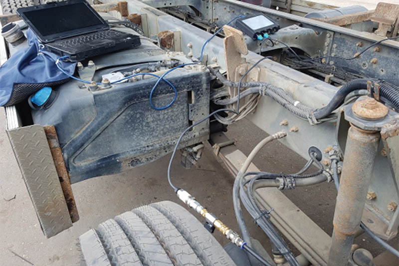
Connecting the transducers to the air pressure test port needed a little creativity. Pico does not have the accessories at present, but our BNC+ pressure transducer can be “adapted” to connect to existing test equipment. With everything set up, cables tidied and secured the road test was next. Whilst on the road, various braking styles were used, along with the customer’s concern during light braking. The waveforms tell you all you need to know.
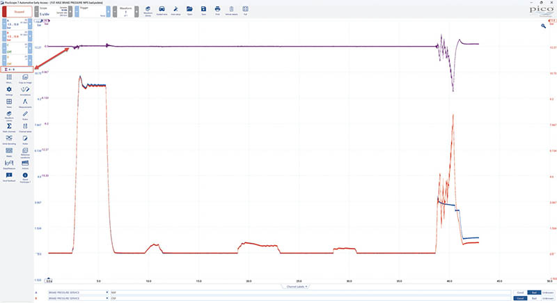
At point one, we applied the brakes quite hard. Both OS and NS air pressure are equal, and the truck brakes in a straight line. Around point 2, there are some very light brake applications, but you can see that both are still equal. At point 3, another partial application of the brake pedal, but this time, you can see the fault. You can see that the blue channel NS is unresponsive compared to the red channel.
Graphing it out
This data can then be saved and analysed for further detail. As we are looking for an imbalance, in an ideal world, both sides should be operating the same; therefore, if we subtract one from the other, the NS and OS should cancel each other out. By adding a built-in math channel to subtract the Blue and Red channels, A and B, we can see the difference.
The math channel further highlights the differences between the NS and OS brake pressure. We can even see some differences when all appears OK. After some further checks for power supply and ground to the modulator, the diagnosis was a faulty modulator.
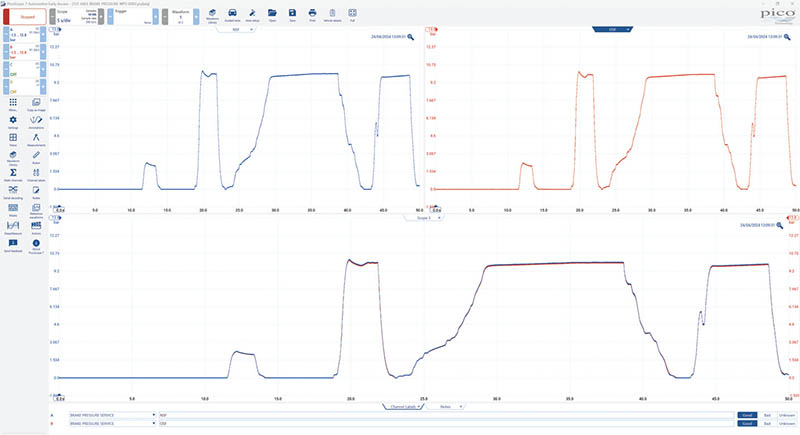
With the modulator replaced, the most important thing now is to repeat the test and capture the verification, which proves the repair, or at least that something has changed. This, of course, justifies the work done. Within the PicoScope software, different viewport options can help highlight the NS and OS air pressure, as well as showing both sides overlaid.
As we can see, everything is even from both sides, and even the math channels show little difference between left and right. The customer confirms that the truck now behaves as expected and no longer pulls to one side when braking in certain situations.
Being able to graph the air-brake pressure in real time and then being able to store the results has benefits to both technicians and customers.