Ben Martins of Pico walks through the process of diagnosing a misfire in a Renault C460 lorry fitted with D11 engine.
The customer complained of poor performance and vibration which feels like a misfire. There were no warning lights on the dashboard, which is interesting as you would assume a misfire would log a DTC. The complaint was verified and we moved on to testing.
For misfires, one of the quickest tests you can do is a relative compression. Whilst not conclusive, it can be used to determine which path to take in the testing, and the best part is the fact that you don’t have to remove any parts to perform it.

By using the guided test, the suitable set up and trigger are already applied for you. All that is required from you is to prevent the engine from starting, connect the PicoScope, and make sure that the current clamp is switched on, zeroed, and clamped around a battery cable that carries current to the starter motor circuit. With the engine unable to fire, you crank it.
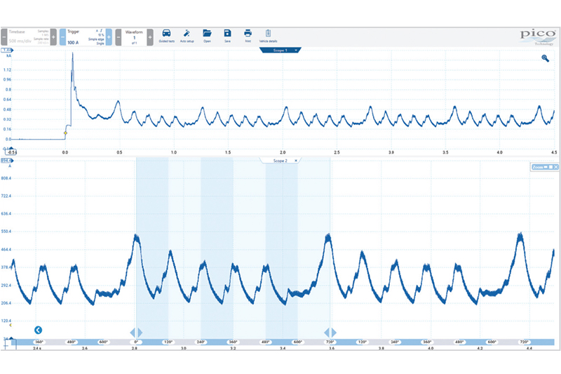
We could immediately see that there was an issue and, more importantly, that it was repeating (Fig. 2). By using the rotation rulers, we can see that there was a lack of current associated with a cylinder. We know this because each time a piston moves up in a compression stroke, the starter motor requires more current to keep turning the engine.
If there is less or no current required during what would have been a compression stroke, then we should first focus on this cylinder to determine the cause. The next challenge is how to identify the cylinders.
The easiest way to identify cylinders is to use an identifier for a known cylinder or, as it’s more commonly known, a sync. For petrol engines, you could use an ignition trigger, primary or secondary ignition pattern, but for diesel engines, you only really have one choice: an injector.
Petrol engines tend to be less picky about whether or not they spark during cranking, but diesel engines tend to want to see a certain amount of fuel pressure before they will send a signal to fire an injector. During a relative compression test, we need to stop the engine from starting. The quickest way is to stop the fuel or to disconnect the injectors. However, that means we lose our sync signal. What now?
A search in the waveform library returned no results for Renault C; however, Renault and Volvo trucks use the same powertrain. Under Volvo, we broadened our search by filtering with some basic information: vehicle make, primary fuel, and capacity. The D11 is a 10.9-litre, and, unfortunately, we found no usable waveforms.
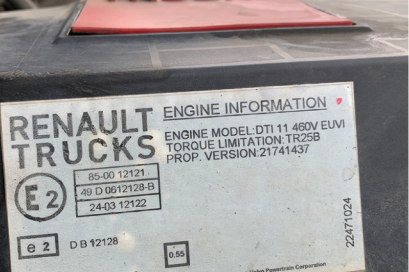
However, through the technical information (Fig. 3), we found that the timing for both the D11 and D13 engines are the same. When amending the engine size to 13-litres, we found the one we were looking for: injector 1 with the camshaft signal.
Looking at this capture with the camshaft signal and an injector signal, we could use the camshaft to determine cylinder 1, and then use the firing order to associate the other cylinders.
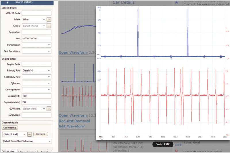
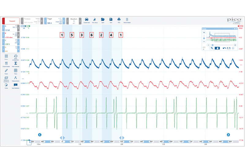
Next, we needed to perform another relative compression test using the same setup but adding another channel; in this case, the camshaft sensor (Fig. 4). From the known good waveform, we knew that cylinder 1 fires first after the double pulse reference on the camshaft sensor.
As we had the option to add another channel, it is always a nice addition to grab the exhaust pulse as well. Remember that the exhaust pulse is as a result of all of the following: intake, combustion, and exhaust. We would expect a nice, uniform waveform if all things are working as they should.
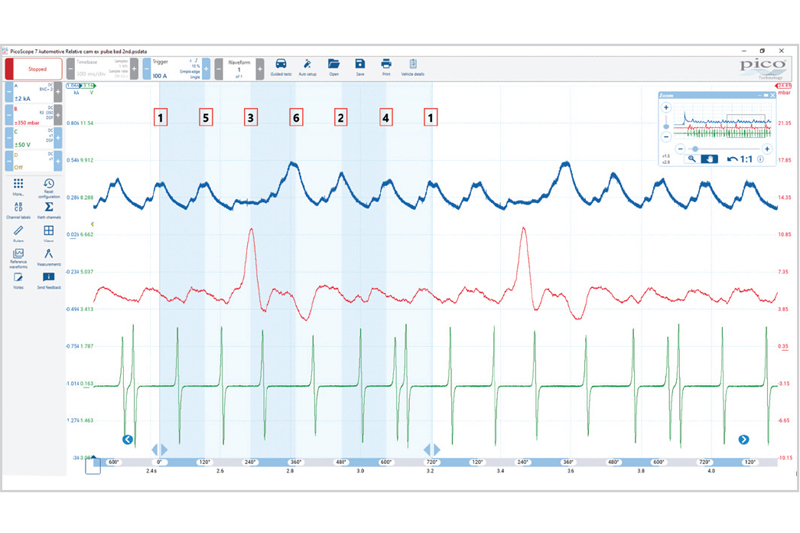
Clearly, that wasn’t the case (Fig. 5). We’ve now used the camshaft to identify the cylinder with the lack of current draw during compression. We knew that cylinder 1 was the first to fire after the double pulse on the camshaft and, by using the firing order, we could identify the remaining cylinders.
We noticed that the exhaust pulse was not even and, at this stage of the diagnosis, that’s all we need to know. We could spend another 30 minutes trying to work out what was going on but, ultimately, that’s not going to fix the truck. From everything we had gathered so far, we needed to look at cylinder 3.
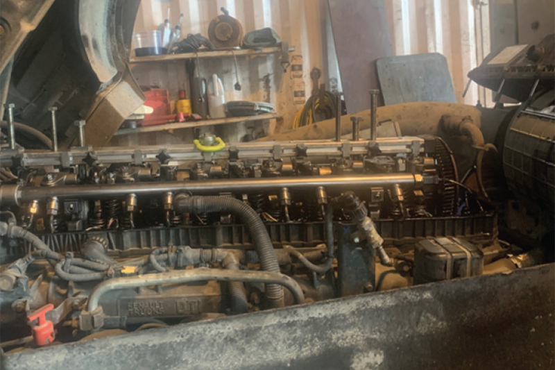
When we removed the rocker cover, things became clear relatively quickly (Fig. 6).
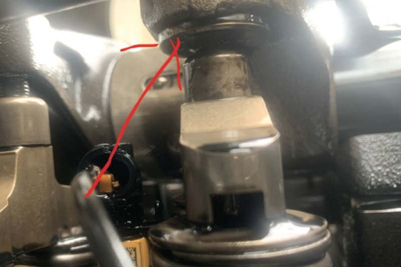
What you can see here in Fig. 7 is the exhaust valve of cylinder 3. The adjuster had moved out much further than the others and, in doing so, was holding the exhaust valve partially open. The lock nut had come loose allowing the adjuster to wind itself out.
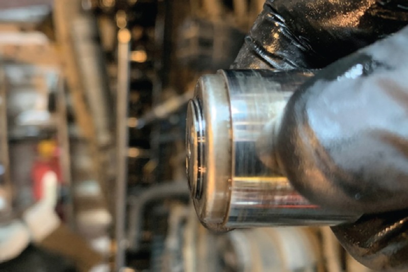
We removed the adjuster to make sure there wasn’t any damage to it. You can see in Fig. 8 how close it was before the locknut fell off completely. With no signs of damage, we refitted the adjuster.
We checked all the valve clearances and adjusted them to the correct setting, according to the technical information. We also applied some Loctite to the locknuts too, hopefully preventing this issue from occurring again, and torqued them to the correct setting.
After installing the rocker cover, it was time to carry out the relative compression test again to see if the fault was fixed. Fingers crossed that the exhaust valve hadn’t hit the piston.
Everything in this waveform is much more even and the exhaust pulse is now uniform (Fig. 9). The misfire was gone and the truck was back on the road again. But what was happening in the exhaust?
With the fault now fixed, we had the opportunity to refer back to our original captures to better understand and, therefore, learn what was happening to create the patterns we were seeing. Let’s refer back to the capture with the WPS500X in the exhaust (Fig. 5).
We know that cylinder 3 was the dead cylinder, but there was a large pulse in the exhaust at the same time. It’s important to think about what was happening in the exhaust whilst cylinder 3 was coming up on its compression stroke.
Cylinder 4 is also coming up the bore but on its exhaust stroke, but at the same time, cylinder 1 is beginning its exhaust stroke. We now know that the exhaust valve on cylinder 3 was being held open which means we have two, possibly three, cylinders travelling up the bore at the same time. However, now they are all contributing to the pulse in the exhaust.
Any form of pressure pulse analysis is difficult as there are often many variables to consider, such as manifold designs, VVti control, exhaust after-treatment systems, and turbochargers.
All of these variables can affect the pressure waveform. Getting known good waveforms where and when you can means looking for the odd one out, making it easier for you to recognise it when you see it.
We usually suggest that Pico users practice using their PicoScope on known good vehicles. If it’s just capturing injector 1 and a camshaft signal, great. If it’s a fuel pump current from inside the fuse box, perfect. This will build the confidence needed to use the PicoScope for the trickier jobs when they come in.
You will also build a nice collection of known good waveforms that you can use for reference. If you then upload these to the waveform library, you have a secure place to store them, and others can use them for their diagnostic purposes too. The alternative for when there isn’t a known good is to refer to the technical information.
Sometimes stepping back from the waveform and just seeing it as what’s good and what’s bad is often all you need to get better direction.