Last year in CVW, BPW looked at specific cases of trailer brake diagnostics. In the second instalment of the two part series, the company sheds light on the analysis techniques and diagnostic procedures that should be employed when investigating a trailer brake abnormality.
In order to understand what follows, it is necessary to understand the basics of the calculations that are carried out in order to set the braking parameters for each trailer. The engineering department at BPW offers a Brake Calculation Service to the trailer builder in order for them to submit it with their type approval documents. Pressures in the braking systems on the tractor and the trailer are referenced to the pressure in the yellow service connection (coupling head) between the two, as this is the only point which is common to both systems. We call this point ‘pm’.
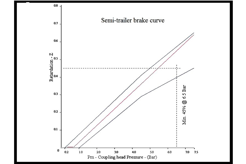
During calculations, variables such as wheelbase, the centre of gravity height, weights and tyre size are taken into account. The calculation produces a graph of retardation versus coupling head pressure. If you look at the typical graph for a laden semi-trailer in Fig.1, you will see that the performance curve (the red line) lies between two blue lines which form an upper and lower bound. We refer to these blue lines as the braking corridor. For semitrailers, the performance at 6.5 bar ‘pm’ has to be a minimum of 45%.
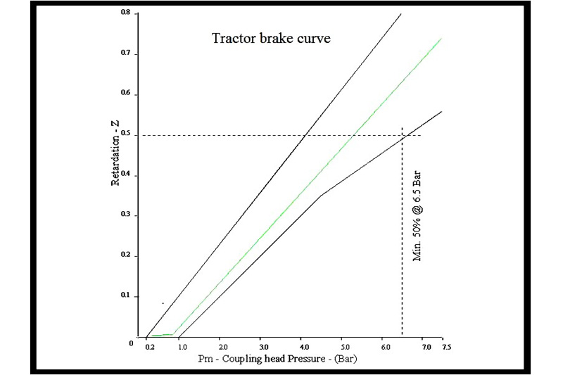
There is a similar graph for the tractor units, and a typical one is shown in Fig.2. In this case, the performance curve is shown as a green line in a black bounded corridor. For tractor units, the performance at 6.5 bar ‘pm’ has to be a minimum of 50%.
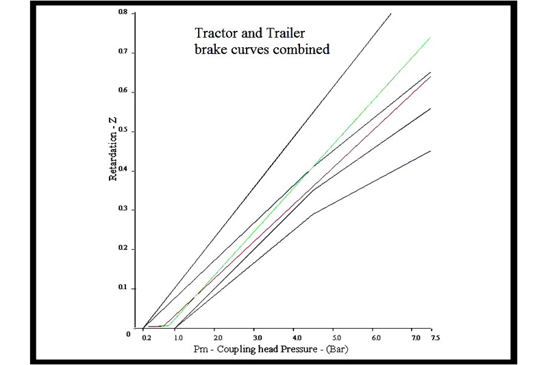
If the balance of braking between the tractor and trailer is equal, then the two braking curves would be coincident. Any disparity between the two curves means that either the tractor or the trailer will be predominant when braking. If we superimpose the typical tractor and trailer curves, we get the situation shown in Fig.3. A closer inspection of Fig.3 will show that the tractor and trailer curves are only coincident at a pressure setting of 1.5 bar ‘pm’. In fact, this situation is quite normal: 95% of all brake applications occur at a ‘pm’ pressure of less than 2 bar. So, you will see that if we can achieve coincidence or compatibility in this region of the graph, then we will have taken a huge step in achieving a tractor/trailer combination, which has balanced braking.
EBS systems
In most EBS systems, there are two sets of data. There are the parameter settings that control how the trailer will behave under braking, and there are the on-board diagnostics that record a history of braking events. If we are called to investigate a braking problem where simpler diagnostic methods have failed to locate a cause, then there may be clues within the EBS system. In order to look into the parameter settings and the on-board diagnostics, the PC interface and software supplied by the manufacturer of the EBS system are required.
The first thing to check is that the parameter settings agree with the calculation for that particular semi-trailer. An experienced engineer will know if the parameters are ‘normal’ for the type of vehicle and operation that is under investigation. Any abnormality here will be compared with the evidence shown on the friction surfaces, and it may only be necessary to make adjustments to the brake calculation and parameter settings in order to restore normal brake operation. Further information may be available in the onboard diagnostics log. Here, we would be looking for any of the following:
- Evidence of abnormally high (or low) braking pressures
- A high number of ABS cycles
- A high number of roll stability cycles
- Overloading (or insufficient loading)
- Driving over speed
Again, any abnormality will be compared with the friction surfaces and parameter settings, and steps can be taken to rectify the situation with adjustments to the parameter settings. Sometimes it’s necessary to consult with the manufacturers of the tractor units if the braking demand from the tractor is too high (or too low). In a typical braking manoeuvre, the tractor unit has control, and it can vary the balance of braking between the two halves of the combination by adjusting the ‘pm’ pressure to increase or reduce the amount of braking on the trailer.
Damaged friction material may take a long time to recover and in some cases may not recover at all, so after adjustments have been made, the friction material may have to be replaced in order to see the effects of those adjustments.
Dynamic testing methods
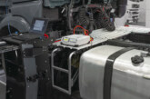
In stubborn cases, we have to resort to dynamic testing. In the days of ABS braking systems, it was sufficient to check tractor and trailer balance with pressure gauges connected to key points within both braking systems. These tests were conducted with the vehicle stationary. With EBS systems, the tractor unit modifies the brake settings dynamically during journeys, so static testing is no longer valid. In these cases, we use dynamic, real-time testing equipment that can measure air pressure, friction surface temperature, speed and acceleration on both the tractor unit and the trailer. The data is continuously sampled and collected by a laptop computer in the cab of the tractor unit. This process normally takes three days; the first day is spent connecting the instruments onto the vehicle, the second day is spent running the vehicle over its normal operating routes, and the instruments are removed on the third day.
It will take several days to analyse the data that will be gathered during these tests. During the testing process, parameter settings on the trailer will sometimes be changed and the effects observed whilst running. If we are working in conjunction with a tractor manufacturer, they too may make parameter adjustments and then observe the effect of their modifications. This process of adjustment and re-test can sometimes cure the problem and no further action will be necessary. In most cases, however, the data will be analysed and following discussions, changes will be recommended. After a period of normal vehicle uses, the friction material will be inspected in order to see if the problem has been resolved.


