Ben Martins, Automotive Application Specialist at Pico, talks us through the process of diagnosing a misfire fault.
I was recently asked to take a look at a 12.3L HGV. I was lucky to have assistance on the day, with access to the relevant technical information. A slight misfire had started at idle and worsened over time. A heavy diesel knock was present when started up from cold. There were no warning lights, but a strong fuel smell with smoke. It all improved as the engine warmed up, but with the engine at idle and the crane in use over time the symptoms returned.
The way this engine injects fuel is very different from typical systems. It has individual cylinder heads for each of the six bores and the injectors are mechanically operated by a pushrod. The system alters how much fuel is injected and how long the injector is open with four solenoids attached to a fuel gallery, linking the front and rear bank. Instead of using electrically controlled injectors, the diesel pressure acts hydraulically on the injector to determine how much fuel is injected when the mechanical rocker depresses the upper plunger. It has a set of six injectors, three at the front and three at the back of the engine.
It would be really easy to look at all this information and check the controlling solenoids, measure fuel pressure or look for a leak of pressure. However, in this particular case, I chose to check DTCs first.
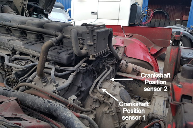
Despite there being no warning lights, there could be stored fault codes which could steer us in the right direction. A quick scan of the ECM found a crankshaft sensor rotation code. Referring back to the technical information and wiring diagram, there were two inductive crankshaft sensors. There is no camshaft sensor as it’s a fixed gear. Timing is done by fuel. Apart from a rail pressure sensor, there isn’t really anything to monitor the injection.
I decided that a potential issue with a crankshaft sensor needed to be checked out first. Something must have happened to trigger the code. The scan tool didn’t say was which sensor to look at, so we used the wiring diagram to find the connectors.
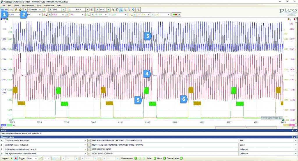
As this test would only utilise two channels, I used the other two to look at the current draw from the timing solenoids, providing a rough trigger point for each cylinder.
1. ±50 V due to inductive sensor.
2. AC coupled for inductive sensor.
3. Ch. A LH crankshaft sensor.
4. Ch. B RH crankshaft sensor.
5. LH Timing Solenoid.
6. RH Timing Solenoid.
Channel B has a good waveform pattern, with the typical AC signal and the gap for crankshaft position reference. This is not the case for Channel A, which has no gap, but two smaller pick-up points with an odd reverse effect on the lower half of the signal. I had the chance to capture a known good waveform from one of the other R480 engines on site to use for comparison, where Channel A was massively different compared to our faulty vehicle.
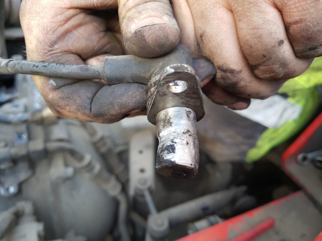
This was enough evidence to remove the sensor for inspection. The fault code didn’t give enough detail as to which sensor was faulty and without the scope we could have wasted time removing and replacing the wrong parts. We also decided to remove the inspection plate between the crankshaft sensors, which revealed more than expected.
There were drilled holes used as teeth for the flywheel and the missing teeth, a non-drilled section of the flywheel. We also saw damage to the ring gear. This could be down to a number of reasons which would have been nice to explore, but the company needed the truck back on the road. Once the sensor was removed it was quite clear there was damage. We fitted a new sensor and re-tested.
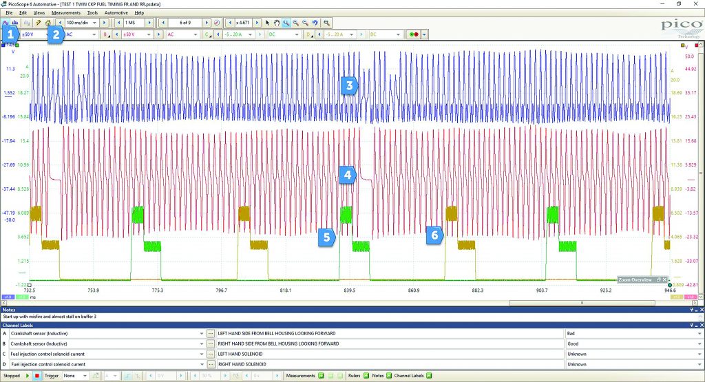
1. Same settings as before.
2. Ch. A LH Crankshaft sensor.
3. Ch. B RH Crankshaft sensor.
The trace is a lot cleaner and the misfire improved. The smoke and smell of unburnt fuel and the sound of diesel knock were also gone. There was still a slight judder in the mid-RPM range but the technician I was with said he wouldn’t replace more parts until he had done a top end adjustment. He believed a lot of the leftover judder could be eradicated with this procedure. After clearing the codes and doing a re-check, the crankshaft code didn’t reappear and the truck went to work.


