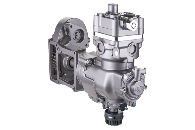
Clutch compressors are a new generation of air compressors now appearing in greater numbers of trucks and buses. Knorr-Bremse explains the benefits and how they work.
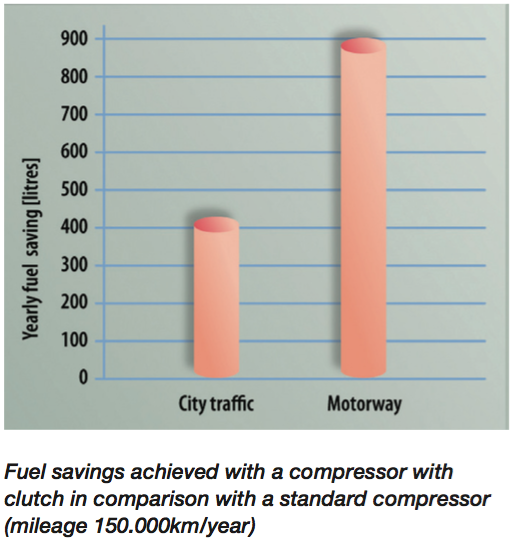
Clutch compressors have been widely adopted by truck and bus manufacturers – MAN, Scania, Volvo and Iveco all fit this latest design. The main attraction for OEMS (and, indeed, operators) is that because of the way they are designed to operate, clutch compressors bring significant fuel savings: we calculate a truck’s CO2 emissions are reduced by up to 2.5 tons per year, with an average reduction of diesel fuel consumption by up to 1,000 litres per year for a long-haul vehicle.
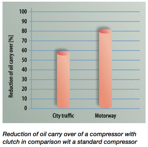
Unlike compressors using conventional technology, clutch compressors avoid the idle running phases. Instead, there are standby periods during which the engine output is physically separated from the compressor, thereby saving energy. Reduced oil carry-over also helps increase compressor life.
How it works
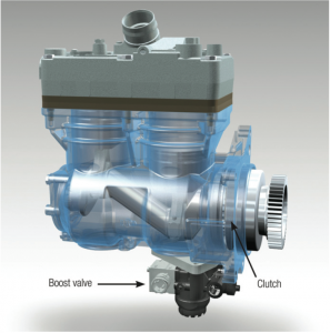
The Knorr-Bremse clutch compressor is a single cylinder design 360cc with up to 12.5 bar operating pressure. It has a watercooled cylinder head jacket and a pneumatically operated clutch. The clutch has an intelligent electronic control function which disengages the drive to the compressor during the part of the duty cycle when there is no air demand.
The drive gear is connected to the engine and transfers the torque to the driveshaft with the clutch housing. The driveshaft runs in sliding bearings, connected to the clutch via a toothed housing. The clutch is screwed onto the crankshaft and is controlled using the actuation piston, sealing compressed air on one side and oil on the other. The crankshaft drive converts the rotary movement into an up-and-down movement. The force is then transmitted through the piston bolt to the piston which slides up and down in the cylinder.
Function
1. Delivering phase
As the piston moves downwards, the intake valve on the valve plate opens and ambient air flows in through the intake connection. Once the piston reaches its lowest position, the intake valve closes, and the piston starts its upwards movement. During the upwards movement, the air is compressed in the even smaller space between the piston and the valve plate.
Once a certain pressure has been achieved, an outlet valve in the valve plate opens, forcing the compressed air through a pressure connection into the pressure line. The bearings are lubricated via the engine oil circulation system: oil channels in the housing and the crankshaft allow the lubricating oil to reach the sliding and connecting rod bearings.
The other bearing points are lubricated by sprayed oil or the oil mist in the crankcase. The cooling water flows through connection into the cooling chamber of the cylinder, the cylinder head) and the valve plate), so that the heat generated during compression process can be transferred through the walls and the intermediate plate into the cooling water. The coolant leaves the cylinder head through connection.
2. Clutch opens
Once the cut-out pressure is achieved, a connection in the air dryer is vented. At this state, the pressure switch trips, activating a solenoid. Pressure is increased on the actuation piston which presses the release bearing against the clutch. The clutch breaks the connection between the driveshaft with clutch housing and crankshaft.
At this point, the entire crankshaft drive and the piston are no longer driven –it’s this feature that is new on clutch compressors and which delivers the fuel savings. In a conventional air compressor, the crankshaft and pistons would still be going round, even when not under pressure.
 3. Clutch closes
If the pressure in the system falls below the cut-in pressure of the pressure regulator, the pressure switch interrupts the actuation of the solenoid. Pressure is decreased from the actuation piston, the clutch closes and the compressor delivers air again.
The condition of the compressor with clutch depends primarily on its peripherals. This means that the air filters, intake lines, pressure lines, any leaks in the system, oil quality, oil pressure and the cooling system of the compressor must be in error-free condition. The function of the clutch (21) is checked by filling the system until the cut-out pressure is reached.
After the compressor drive is disconnected at the clutch and regeneration is complete, no compressed air should emerge from the ventilation of the air dryer.
4. Servicing
Maintaining clutch compressor performance depends primarily on ensuring peripherals such as air filters, intake lines, pressure lines, leaks in the system, oil quality and pressure and the cooling system of the compressor are kept in good condition.