In the first of a two-part series, Ben Martins, Automotive Applications Specialist at Pico, describes how he approaches a DAF CF that is repeatedly cutting out.
It seems that a lot of the faults I come across these days are communication based, and this vehicle is no different. Having a solid understanding of how an automotive network is created is becoming increasingly important, but fundamentally it is just about voltage. Don’t panic straight away, just because there are 30 fault codes all shouting communication issues. There are some simple and basic things we can do to determine what is going on, and with PicoScope, we can delve even deeper.
Talk to the customer
Talking to the customer is one of the most important tasks in any diagnostic job. They have all the information about the vehicle and may hold that key piece that was missed on the job card. The complaint this time was: the vehicle suddenly cuts out and then fails to restart.
Using a little intuition may help in this situation, so open-ended questions can lead to further information from the customer. Keep them talking. Ask them about the weather, how long they were driving, if this fault has happened before, if any other work has been carried out recently, any warning lights on the dash before the fault happened, the speed they were doing, what gear, and so on.
As it turned out, the important bit of information I got from these questions was that the vehicle was fine from cold, but after driving for some time, it suddenly cut out. They then waited for the recovery services who naturally attempted to restart the vehicle, and behold; it started! However, setting off with the recovery services following, it wasn’t long before the engine cut out again. It would be wrong to assume anything at this stage, but I thought we could be looking at a temperature-related fault.
Vehicle inspection
Inspecting the vehicle the next day meant that it had plenty of time to cool down and we were able to look at the vehicle in the same conditions as the driver did right before the fault occurred. Also, you should never overlook serial diagnostics if you have the opportunity to take a look. They can often point you in the right area but may not always have the answers. In this case, we had 12 active diagnostic trouble codes, with 11 reporting CAN communication faults. To add further detail, four of these were directly pointing to the engine ECU. While not completely obvious, it provides at least some direction. With this in mind, I felt it was necessary to observe the CAN lines to the engine ECU.
Verifying how the network is set up is a must at this point, as there are several networks on all vehicle types. This could mean that an ECU of interest might not be on the network you are connected to, so always double-check a wiring diagram. In this case, the ECU of interest was the engine ECU and it happened to be involved in a number of networks, including the one with the OBD port in it. This network was a typical setup, utilising two 120Ω terminating resistors joining CAN H and CAN L together. These will normally be situated in an ECU at the end of the network, and so a simple resistance check on the CAN network can be carried out to verify its integrity.
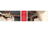
Here, I could utilise the breakout box to easily gain access to the terminals, but I could also confirm the network was no longer active and had shut down. It is good practice to only carry out a resistance check to a network when it is no longer active, which normally means you would disconnect the battery to prevent the network from waking up. Disconnecting the battery on this vehicle was not practical due to some additional equipment fitted, so observing the breakout box LEDs for inactivity was the next best thing. I could also use the PicoScope to watch and wait for the network to shut down to be completely confident, but as I said, best practice is to disconnect the battery.
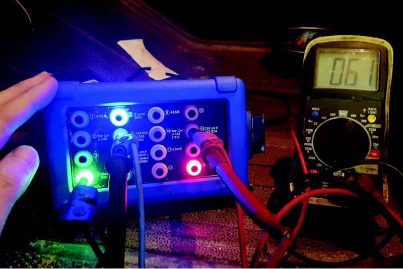
With the network no longer active, a quick resistance check saw the magic 60Ω you would expect to see from two 120Ω resistors in parallel (Fig.1).
Next on the list was to try and catch the fault in action. For this, I used PicoScope’s ability to capture against time and, hopefully, catch the point when the fault occurs. I didn’t strictly follow the CAN diagnosis tests in this situation, as I wasn’t dealing with a typical fault, although the first stages of verifying the integrity of the signal remain. The new guided test on how to test the CAN Bus physical layer, is available by clicking here.
Capturing the fault
Moving on, I wanted to extend the time to allow for more data on the screen. I’ve used 2ms/div, which gives me more time in total, but also allows me to maintain enough detail to decode on.
If you’ve followed any of Pico’s previous case studies, you will often hear us talk about using math channels to aid with CAN diagnosis. We utilised the inbuilt math of A+B and A-B to get a better understanding of the network, and to decode the signals in the same way the controllers did. It also helped to show us the resilience of CAN and how even with interference, the messages still got through without being affected. You can find the Math Channels by clicking Tools > Math Channels. A dialogue box will open where you can select the inbuilt Math channels.
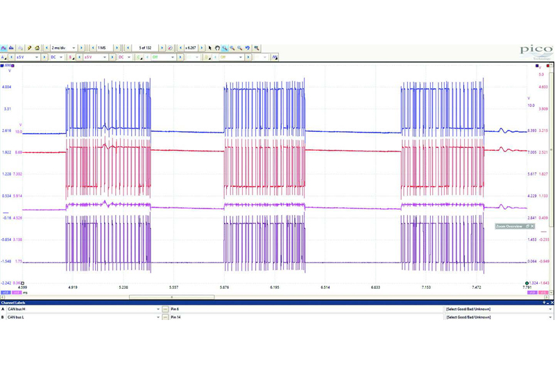
As you can see (Fig.2), I’ve zoomed in on three messages. CAN H is on Channel A, CAN L is on Channel B and underneath, we have one result of adding CAN H to CAN L, and also one where CAN L has been subtracted from CAN H. You will notice that there is some interference on the CAN lines. It is picked up quite clearly in packet one on the A+B channel, but when you subtract them the way the CAN controller does, any interference that was there no longer exists, proving the CAN’s fault tolerance.
Something else I’ve noticed, having looked at a few HGV and off-highway vehicles, is that the networks allow for a lot more interference. Normally with cars, when you add CAN H to CAN L, you end up with a very straight line at 5V (2.5V+2.5V= 5V and 3.5V +1.5V= 5V.) With trucks, there always seems to be an allowable deviation of the 5V. It’s never a huge amount, but can be up to 0.4V. However, when we look at the physical layer, A-B, everything is very even and allows us to use the inbuilt serial decode tool.
A question I often get asked is what the spikes at the end of each byte are, and is this something to be concerned about? The spikes, or ringing, can be down to a number of factors, but they are most often down to a limitation of the test leads. In order to eliminate these, it is advisable to use the 60MHz scope probe, which will give a much cleaner signal. There are differences between the two leads. However, providing we know the limitations and are happy that what we are seeing is acceptable, we can continue with the testing.
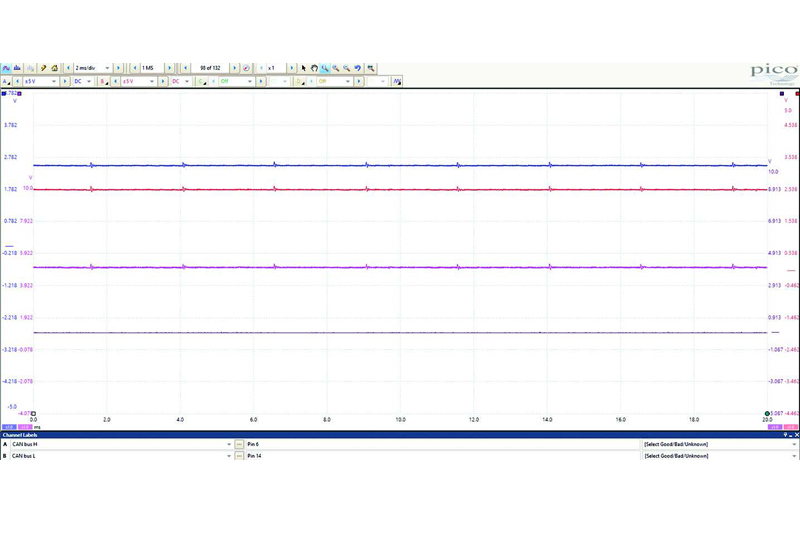
After running the truck back up to temperature, I started to experience the fault, with a slight hesitation, before the engine suddenly stopped – just as the customer had described. Leaving the scope to continue capturing after the event meant we had both pre- and post-data to look at (Fig.3).
What I saw was complete network silence for two buffers, which totalled at 40ms, before a single packet could be seen along with further silence. What I noticed, is that there was significantly less CAN traffic on the network. So, what now?
Keep an eye out for the September issue of CVW to see how Ben solves this DAF dilemma.