ZF Aftermarket provides a best practice step-by-step guide to replacing a HGV brake caliper.
The latest Driver and Vehicle Standards Agency (DVSA) statistics show that over the past four years, brake system components and service brake performance have consistently occupied third and fourth position respectively in the top ten reasons for heavy goods vehicle failures during the annual test. To encourage improvement via best practice, ZF Aftermarket offers expert advice on inspecting and replacing components of the service brake, in this case the brake caliper and brake pads. Some of the steps described may vary depending on the brake system and vehicle manufacturer.
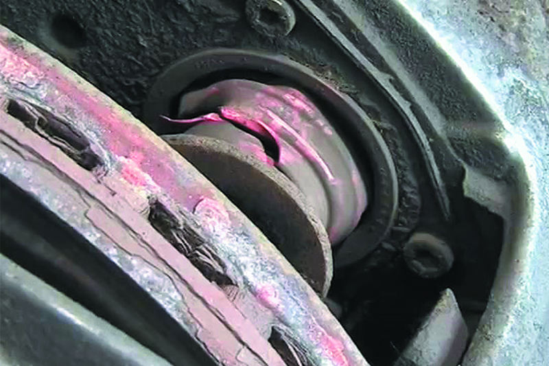
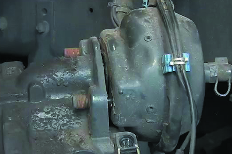
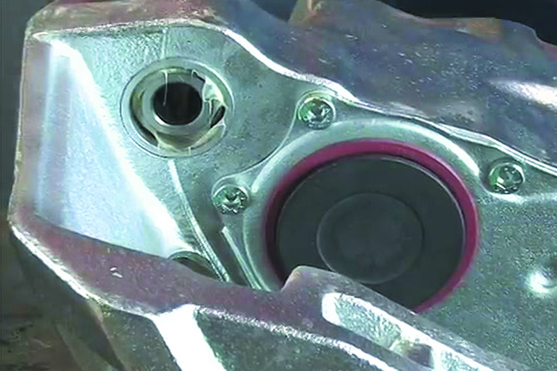
Replacement of a brake caliper on an HGV may be necessary if an inspection of the braking system or routine replacement of the brake pads highlights a problem. This could be due to corrosion or wear of the caliper guides causing brake binding or reduced braking effort, or when a defective adjuster has been identified. In the latter case, the condition of the piston dust boots (Figure 1) gives useful clues; if damaged, they can allow moisture to enter the mechanism, which leads to corrosion of the inner components and ultimately failure of the adjuster.
Brake pads must be replaced as an axle set; similarly, it’s always advisable to change brake calipers in pairs. Any problems in the braking system on one side of the vehicle are likely to soon be replicated on the other side, given that they have been operating in the same environment for the same length of time.
Gaining access to the caliper
Raise the vehicle and remove the road wheels from the axle to be serviced. Before dismantling, check that the new caliper matches the installed part: compare part number and design, and also the connections of the ABS sensor and brake pad wear indicator.
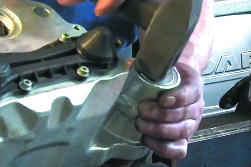
Disconnect the ABS sensor, brake pad wear indicator and remove the brake actuator (Figure 2). The brake caliper pistons must now be backed off manually by removing the sealing cap and turning the adjuster beneath it anticlockwise (the overload clutch in the adjuster will click audibly as its breakaway torque is reached) to reveal the inner brake pad. A new adjuster is included as an accessory with a new set of TRW brake pads.
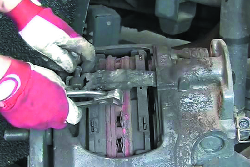
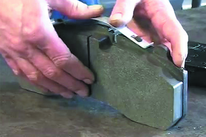
Remove the retaining clip, safety bolt and brake pad retaining bar (Figure 3), and manipulate the caliper as necessary to enable the brake pads to be removed. Undo the brake caliper carrier’s fastening screws, then remove the caliper and carrier assembly to the workbench.
Servicing the brake housing
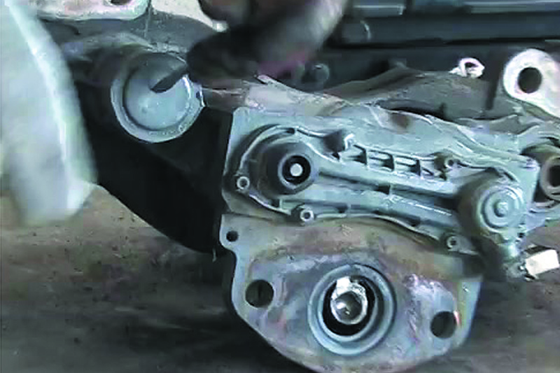
Carefully tap a pointed tool through the metal caps of the caliper bolt guides and use it to lever them out (Figure 4), then unscrew the guide bolts. Remove the carrier and clean it thoroughly – this reduces the risk of the brake pads sticking in the pad slot and causing the brake to overheat.
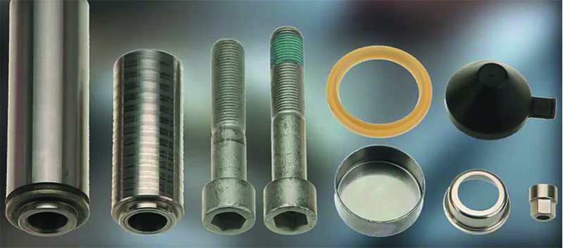
TRW replacement calipers are supplied with all necessary accessories (Figure 5) to simplify the repair process and ensure reliable brake function. Using the supplied grease, lubricate and install the new guide sleeves in the caliper (Figure 6).
Mount the carrier to the new caliper, tighten the bolts according to the vehicle manufacturer’s specified torque setting, then tap the new metal caps into place to seal the guides (Figure7).
Reassembling the brake components
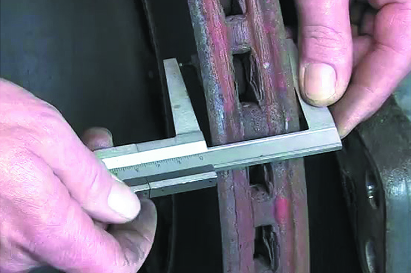
Before installing the new caliper, inspect the brake disc: check for cracks or corrosion and that the thickness is above the manufacturer’s specified minimum, usually marked on the disc (Figure 8).
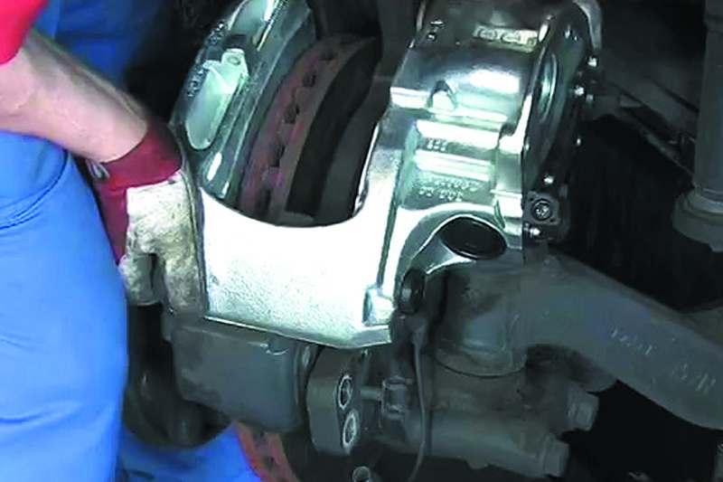
Assuming the brake disc to be in serviceable condition, place the new caliper in position (Figure 9) and tighten the carrier screws to the specified torque.
Fit the supplied pad retaining springs to the new brake pads (Figure 10). Note that the design of TRW’s springs may have changed compared to those removed from the vehicle. However, the new pad retaining spring and the previous TRW or OE pad retaining spring are fully interchangeable.
Install the brake pads and refit the retaining bar, securing it in place with the supplied safety bolt and clip. Finally, refit the brake actuator and reconnect the ABS and pad wear sensor cables.
Adjustment and testing
To ensure reliable brake function, the initial adjustment of the brake caliper pistons must be set manually according to the vehicle manufacturer’s procedures. The following is a general guide to the process:
■ Turn the adjuster in the caliper clockwise until the brake pads contact the brake disc, taking care not to over tighten the adjuster. Now, turn the adjuster back three to four clicks.
■ Apply the brake firmly,then release the pedal and check that the wheel hub can still be rotated by hand.
■ The wheel can now be mounted to the hub, centred and the wheel bolts tightened in a diagonal pattern to the correct torque.
■ Once both calipers on the axle and the set of brake pads have been replaced, braking performance should be checked on the brake test rollers before undertaking a test drive.