Knorr-Bremse explains how to replace the air dryer cartridge and main sieve on the company’s Electronic Air Control Systems.
Knorr-Bremse Electronic Air Control systems provide intelligent air management of the vehicle pneumatic system, controlling the filling of the brake and auxiliary circuits. The latest version, EAC2.5, fitted to Renault and Volvo trucks, incorporates an electronically controlled parking brake, so there are fewer pipes and a reduced risk of pipe defects and leakage. The assembly incorporates air dryer cartridge maintenance prediction and bayonet fittings to make servicing faster and easier.
Here is the step-by-step guide to replacement of the air dryer cartridge and main sieve.
Disassemble
Remove bayonet ring, desiccant cartridge housing, desiccant cartridge interior, locking screw and main sieve.
1. Remove the locking screw (3) – Torx T30. Unscrew the locking screw. (If the locking screw breaks off at the pre- determined break-off point, the remainder of the locking screw can still be removed with a 5mm Allen key.
2. Place two screwdrivers on the bayonet ring clips. Rotate the bayonet ring with both screwdrivers anti-clockwise until it loosens. Slide the bayonet ring over the desiccant cartridge housing.
3. Remove both the desiccant cartridge housing and interior assembly from the valve block. (If it is not possible to remove the assembly from the valve block by hand, insert a flat headed screwdriver in one of the three grooves, and rotate or lever lightly with the screwdriver, but avoid scrapes and deformations at the valve block.)
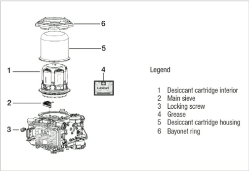
4. Position a flat-headed screwdriver in one of the slots in the desiccant cartridge interior to lever out the housing.
5. Remove main sieve.
Valve block check
Once the bayonet ring is removed, visually check the valve block.
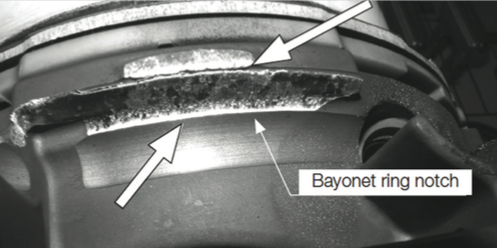
■ If the protective surface is worn down to the base metal or if the bayonet ring notch has any damaged, the EAC2.5 must be replaced.
■ Wear of the sealing area where it contacts the cartridge interior is permissible, as is wear caused by the ribs of the desiccant cartridge interior.
Clean
1. Clean inside and outside of the cartridge housing.
2 Check all the inside surface for corrosion.
3. Check sealing surface for damage. If corrosion is found inside the desiccant cartridge housing or there is damage to the sealing surface, the cartridge housing must be renewed.
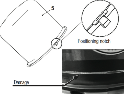
4. Is the positioning notch still intact on the desiccant cartridge housing? Is there any damage on the outside? If these are missing or damaged, the desiccant cartridge housing must be renewed.
5. Clean the bayonet ring. Replace the bayonet ring if the protective surface is worn and/or three or more bayonet ring clips are bent, cracked or missing.
Installation Cleaning
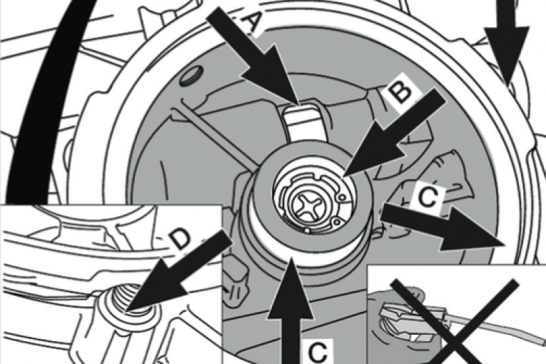
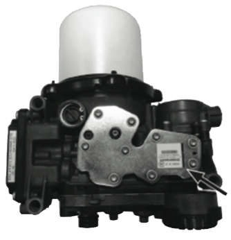
1. Close openings of the safety valve (A) and the non-return valve (B) with a lint free cloth or with sticky tape to help prevent any dirt from entering.
2. Clean the chamber (grey), the sealing surfaces (C), the thread and seal area (D) of the locking screw (3) and the bayonet ring notches (E) to remove all dirt.
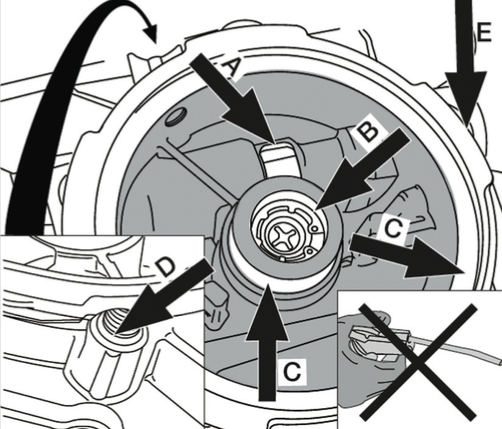
3. DO NOT use compressed air to clean the area in the chamber as this may cause dirt to enter the safety valve (A) or the non-return valve (B) resulting in a malfunction.
4. Check sealing surfaces, inner thread and sealing area for the locking screw for scratches.
5. Check also valve block and replace if damaged.
Mounting
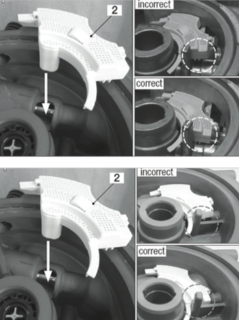
There are two valve block variants of the EAC2.5. Insert the locking finger of the main sieve thoroughly into the opening for the safety valve. If the main sieve has not been inserted correctly it may become damaged when the desiccant cartridge assembly is fitted and the EAC 2.5 will malfunction.
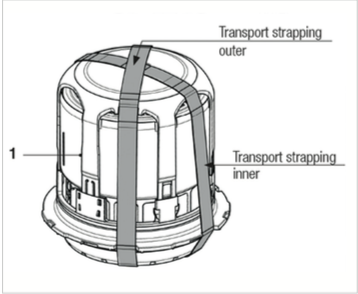
1. Remove the transport strapping.
2. Apply the supplied grease to the sealing elements in the desiccant cartridge interior, but do not alter their position. (Lubrication will minimise the necessary force required when fitting).
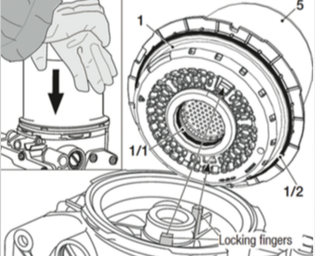
3. Align the positioning notch of the desiccant cartridge housing directly over the desiccant cartridge interior detent and push the housing to engage. The two fingers of the valve block must be aligned with the detents in the desiccant car tridge interior.
4. Push the assembly on to the valve block.
5. Lubricate the bayonet ring, the flange and five lugs.
6. Fit bayonet ring and turn in a clockwise until it clicks into place.
7. Tighten the bayonet ring with two screwdrivers in a clockwise direction as shown.
8. Either grease the O-ring on the new locking screw or lubricate the O-ring sealing area in the valve block.
9. Tighten securely to a torque of 5+1 Nm.
10. Reset the cartridge predictive maintenance to 0 using an appropriate diagnostics tool.