The technical team at INA takes a look at the 2.0tdi Volkswagen Transporter and offers some guidelines on timing belt and auxiliary belt replacement.
The CAAA engine is a Common rail TDI engine. It is fitted in the Transporter and Caravelle which are a very popular vehicle on the UK roads today; not only for business use but also for recreational use, so the likelihood of one of these arriving into your workshop for repair is extremely high.
The timing belt replacement is advised at 80,000 miles or four years and generally vehicle manufacturers have no recommended replacement interval change for the auxiliary belt but INA strongly advise to change these components at the same time as the timing system.
This engine has been identified as an interference type engine, so in the event of a timing belt failure, the likelihood of engine damage is extremely high. It is important to install a new timing belt system on an engine that is at ambient room temperature. Always adhere to turning the engine in the normal direction of rotation unless advised otherwise by the OEM installation instructions. Recommended torque values should always be used. It is recommended that all the tensioners, idlers and fixings are replaced as advised by the manufacturer during the timing belt replacement.
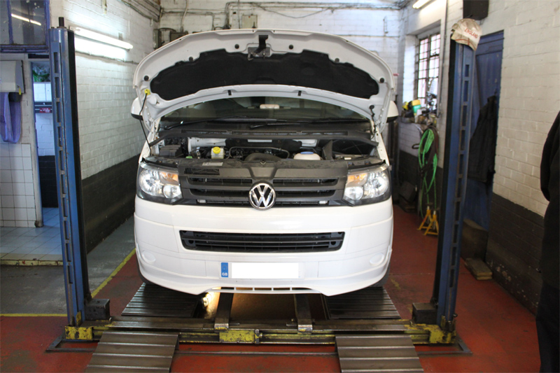
A two post ramp is ideal for carrying out timing belt replacements, but in this instance we used a four post wheel free lift, it is also vital that the appropriate timing belt replacement tools are available and used and these are readily available from most factors. If the vehicle is equipped with alloy wheels it’s a good idea to locate the adaptor key before you start.
Once the vehicle is on the ramp, for safety reasons and best practice we disconnected the negative battery lead.
Open the bonnet and disconnect the Air flow meter and MAP sensor multi plugs, disconnect the breather pipe from the cam cover and remove the complete air filter box assembly and the disconnect the air intake hose from the turbo and remove hose and then remove the upper timing belt cover.
Raise the vehicle, remove the engine under tray, O/S/F wheel and wheel arch liner, remove the auxiliary drive belt by rotating the tensioner in a clockwise direction and locking it with a 3mm locking pin. Remove the four bolts from the crankshaft pulley and remove the pulley, in this instance the pulley had seized onto the crankshaft, we used a universal crankshaft/auxiliary pulley removal tool which proved invaluable and would be a wise investment for any workshop.
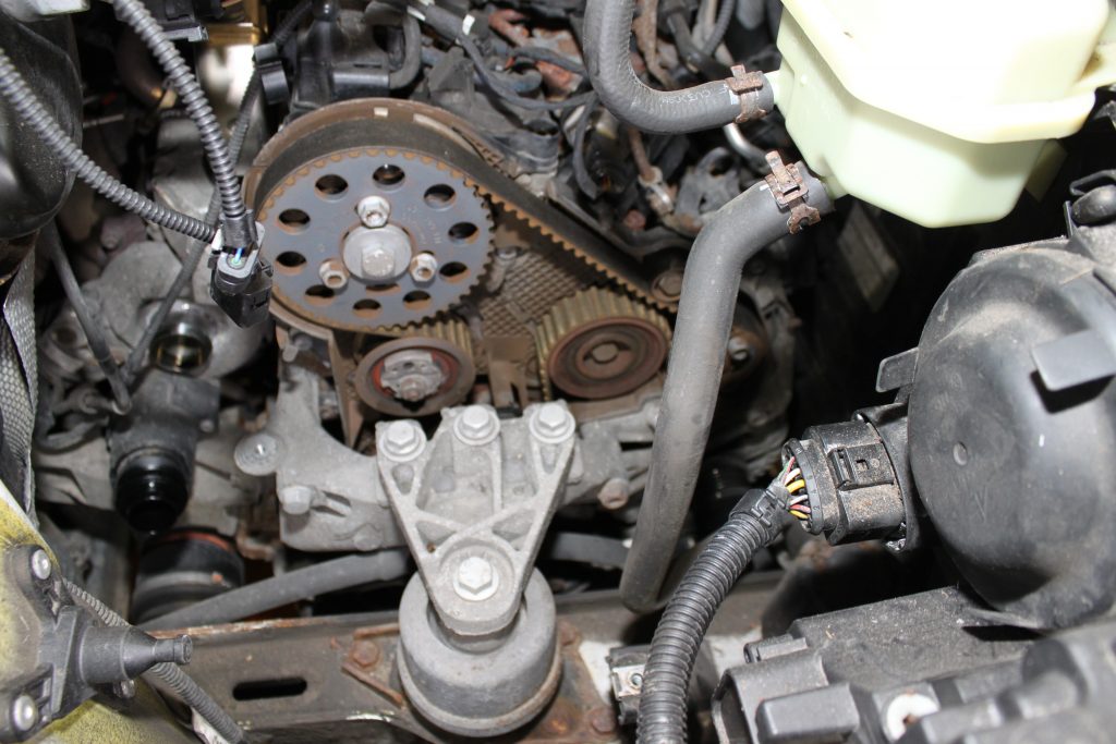
Now remove the upper intercooler pipe from the turbo and the intercooler, at this point we are now ready to remove the engine mount (Fig 1). Support the engine and remove the complete O/S engine mounting as this gives better access and visibility to the timing belt area. Remove the lower timing belt cover which is secured in place with five Torx bolts.
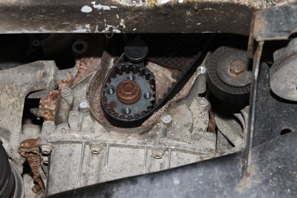
Now with all the timing belt covers removed and good access to that area we can rotate the engine by the crankshaft and align and pin the crankshaft (Fig 2), camshaft and high pressure fuel pump (Fig 3), we must also slacken the camshaft and high pressure fuel pump pulley bolts at this point so that the timing and tension are correct. With the crank, cam and high pressure fuel pump locked, slacken the timing belt tensioner and remove the timing belt and the tensioner.
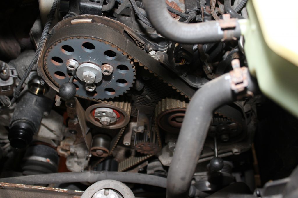
Replace the tensioner stud and torque to manufactures specification, fit the new tensioner and ensure the tensioner locating lug is correctly located and then replace the three idlers supplied in the INA timing belt kit and torque up the new bolts. Replace the three bolts in the camshaft pulley and the three bolts in the high pressure fuel pump pulley and tighten hand tight so the pulleys rotate but do not tilt and rotate both pulleys fully clockwise on the slotted holes.
Now fit the new timing belt starting at the crankshaft pulley, up to the camshaft pulley and then from the crankshaft to the water pump, high pressure fuel pump and then finishing off on the idler between the high pressure fuel pump and the camshaft.
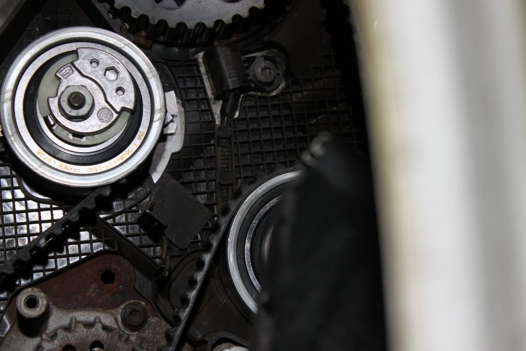
Now tension the tensioner by adjusting it in a clockwise direction until the pointer aligns with the notch (Fig 4) and the torque to the manufactures specification. When the timing belt has been tensioned correctly, the pulleys on the camshaft and high pressure pump rotate to a central position, use a counter hold tool on the pulleys and torque up the adjustment bolts on the cam pulley and the high pressure fuel pump pulley. Remove all locking pins and rotate the engine two complete revolutions, now refit the locking pins in the crankshaft, camshaft and the high pressure fuel pump to ensure the timing marks align and ensure the tensioner pointer aligns.
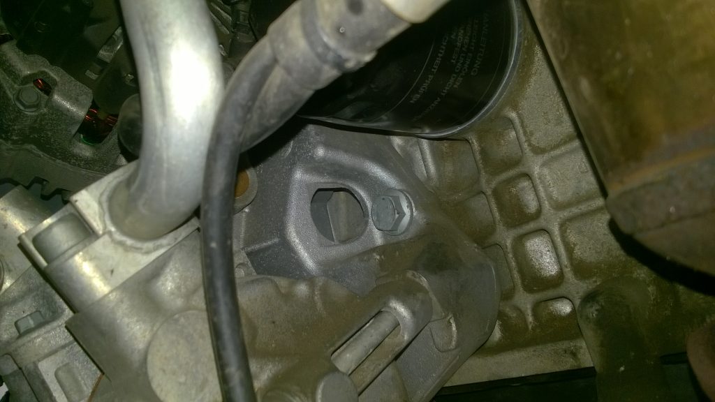
When the engine has been rotated two complete revolutions and all locking pins can be located then install removed components, refit timing belt covers, engine mount and crankshaft pulley. At this point we replaced the auxiliary drive belt tensioner which is retained by one bolt easily removed with a socket through the access point (Fig 5). A new auxiliary drive belt should be installed and then the tension is applied by removing the tensioner locking pin.
Refitting the remaining parts is the reverse of removal.

