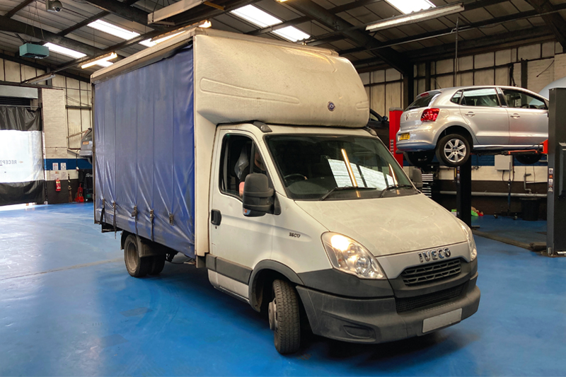
Help is at hand as Schaeffler LuK’s Alistair Mason provides a step-by-step guide to replacing the clutch on a 56,000 mile, 2014 Iveco Daily 35C17.
Vehicle Information
Make Iveco
Model Daily 35C17
Year 2014
Mileage 56,000
Time 4.2 Hours
The advantage of a pull type clutch is that it gives a greater clamp load on the clutch, without an unnecessarily heavy clutch pedal, due to the pivot point/lever ratio of the diaphragm spring being at the outer edge, rather than two thirds or three quarters of the way down the diaphragm spring, and therefore the diaphragm spring must be ‘pulled’ to disengage the clutch. Pull type clutches are generally found in commercial vehicle applications that require the additional clamp load but can also be found in some of today’s cars. The important thing to know and remember when replacing a pull type clutch, is how the gearbox is removed whilst the release bearing stays attached to the clutch. So, ten minutes of wisely spent research can save hours of struggling to remove the gearbox!
Gearbox removal
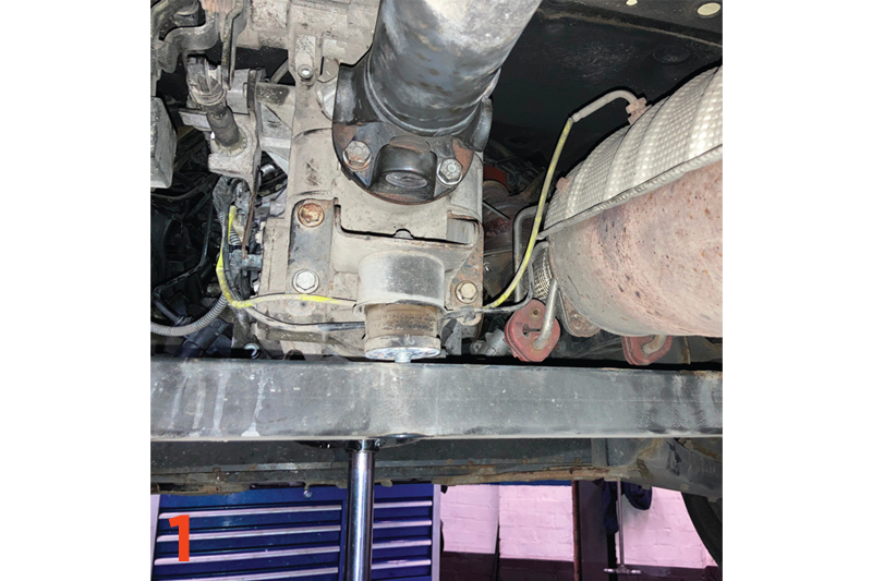
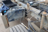
With the vehicle safely positioned on the lift, open the bonnet, disconnect the battery earth lead and stow it safely. This is the only part of the repair that is carried out at ground level, so raise the lift to gain access to the underside, support the gearbox with a transmission jack and then remove the gearbox crossmember by detaching the gearbox mounting nut and crossmember to chassis bolts (Fig.1). With the crossmember removed, disconnect the prop shaft from the gearbox and unbolt the centre mounting from the chassis (note – it is advised to mark the prop shaft flange and gearbox flange position to eliminate any potential balance issues).
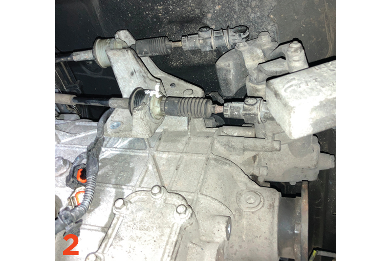
This step gives good access to the electrical multi-plugs on the side of the gearbox, so disconnect them, unbolt the bracket and stow away from the gearbox. The gear cables can now be removed (Fig.2) by levering the cable off the ball joints and then easing the outer cables out of their retaining brackets.
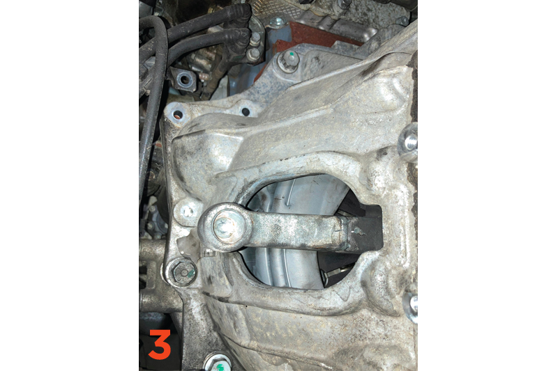
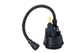
Remove the hydraulic slave cylinder by unbolting the metal mounting bracket and stow the cylinder and bracket away from the gearbox. Detach the rubber boot from the release arm (Fig.3), which allows the release arm to pivot far enough around to disengage from the release bearing when the gearbox is being removed.
Ensure the transmission jack is positioned correctly onto the gearbox and, working around the gearbox, remove the bell housing and starter motor bolts and store them in order of their removal. The gearbox can now be moved away from the engine and at the same time ease the release arm back, so it disengages from the clutch release bearing. Once the gearbox input shaft is clear of the engine and the release arm disengaged, the gearbox can be removed from the vehicle.
Clutch replacement
Remove the six clutch bolts and then the clutch assembly from the flywheel.
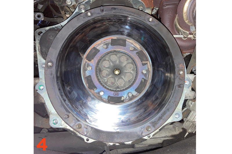
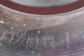
In this example, the clutch fault then became evident as, due to ‘slipping’ and overheating, the clutch lining had become detached from the clutch plate and broken up, which had also caused the dual mass flywheel to be exposed to excess heat, this was evident by the blue colour on its surface, affecting the internal springs and grease (Fig.4), (note – it is good practice to clear and vacuum up the broken clutch lining). At this point the customer was contacted and authorisation to also replace the DMF was given.
Turning to the release system in the gearbox, ensure the bell housing is clean and inspect the release bearing guide tube for any wear, and replace it if there is. Check that the pivot point on the release arm is free and also does not have any signs of wear (note – the pivot points are prone to seizing). Apply a light smear of high melting point grease to the guide tube and onto the gearbox input shaft splines and mount the clutch plate, this will confirm it is the correct plate and will also evenly distribute the grease.
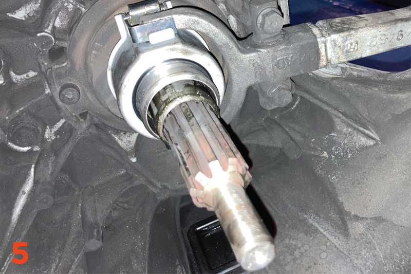
Remove the clutch plate and any excess grease, apply a light smear of high melting point grease to the pivot points of the release arm/release bearing, fit the new release bearing, engaging it into the release arm as it passes up the guide tube and, when in position, ensure the release arm operates correctly and freely (Fig.5).
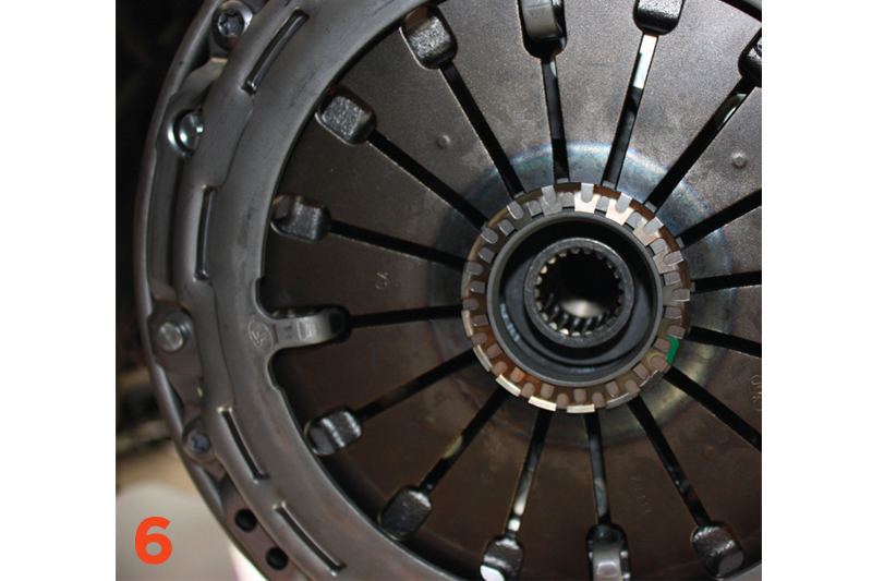
Replace the DMF and torque the bolts to the manufacturer’s specification, then clean the DMF clutch face and new clutch pressure plate face using some brake and clutch dust cleaner. Using a clutch alignment tool, mount the new clutch plate onto the flywheel with ‘gearbox side’ facing away from the engine, locate the clutch cover onto the flywheel dowels, insert the six clutch bolts, tighten them in an even and sequential process and finally, torque to the manufacturer’s specification (Fig.6).
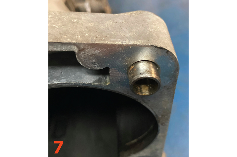
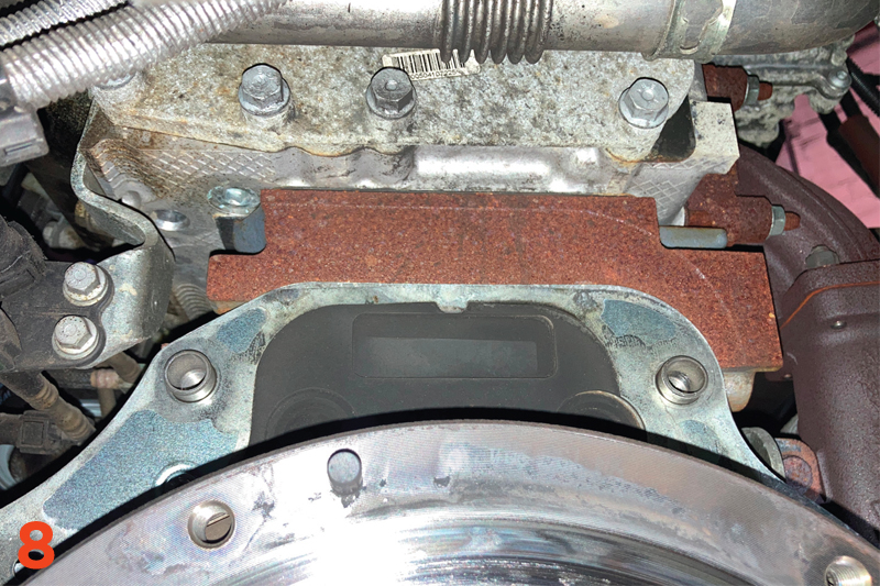
A crucial part of this repair is the alignment between the engine and gearbox so that the release bearing locks into the clutch cover on installation. To ensure this alignment is correct, it is critical that the engine to gearbox alignment dowels are installed (Fig.7&8). So, prior to fitting the gearbox, ensure all the alignment dowels are inserted correctly.
Gearbox installation
Using the transmission jack, ease the gearbox into position, confirm the gearbox is located on the alignment dowels and is tight against the engine, then insert the bell housing bolts and tighten them.
The release bearing then needs to be inserted and locked into the clutch by hand. So, pull the release arm backwards, until the release bearing starts to locate into the clutch. At this point, using a lever, ease the arm further back until it snaps into the centre of the clutch, then pull back and forth on the lever to ensure that the bearing is locked into position, then fit the rubber boot. As soon as possible, fit the slave cylinder assembly and operate the pedal to ensure the clutch operation is correct. Once this has been confirmed, the rest of the installation is in reverse order of removal.
After connecting the battery lead, reset all electrical systems as required and always carry out a full road test to ensure a quality repair has been completed.