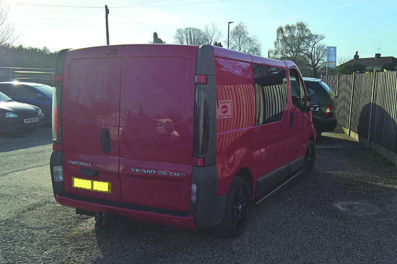
Booked in with complaints of a heavy clutch pedal, a Vauxhall Vivaro 2.5 DTI undergoes a full clutch replacement at the hands of the REPXPERT technicians at Schaeffler.
In this article, the clutch assembly is being replaced due to heavy pedal operation on a Vauxhall Vivaro 2.5 DTI that has covered more than 140,000 miles. There will also be a focus on the clutch fluid bleeding process, after replacing the concentric slave cylinder, as this can be a challenging part of the repair.
The Vauxhall Vivaro is a very popular van, with just under one million vehicles sold from 2001 to 2013, and is especially popular amongst domestic and fleet van operators. The platform for the Vivaro is also shared with Renault and Nissan, so the opportunity for clutch replacement is quite high. The vehicle was booked in to investigate the clutch pedal being heavy in operation, this was confirmed and clutch replacement advised. Prior to starting the repair, ensure you have the locking wheel bolt tool and radio code if required.
The workshop equipment advised for this repair is a vehicle lift, engine support and a transmission jack.
With the vehicle positioned on the ramp and before raising, starting under the bonnet, disconnect the battery, remove the engine cover, disconnect the air mass meter and remove the air filter housing and ducting. Then disconnect the turbo boost pressure sensor multiplug and remove the upper charge air hose and, with these removed, we now have better access to the gearbox area.
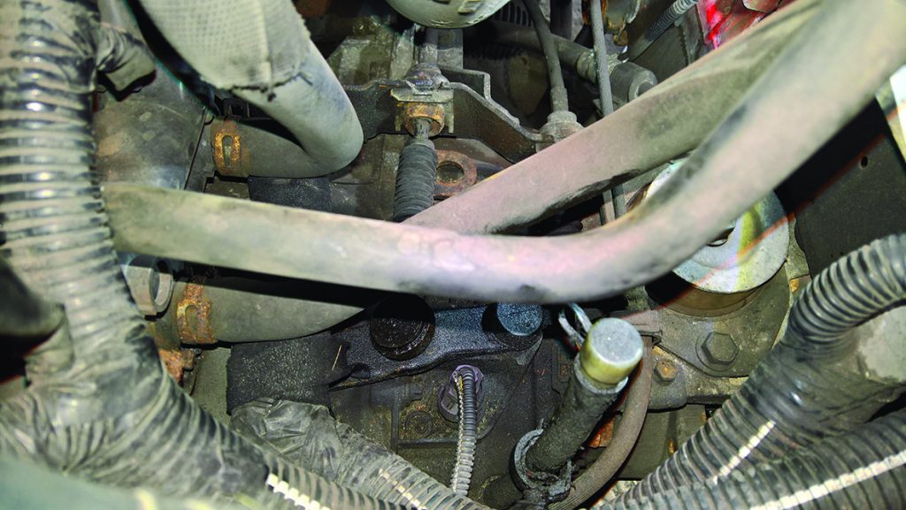
Remove both gear change cables (see below) from the gearbox by pressing in the centre of the nylon ball joint retainers and lifting; then remove the retaining clips on the outer cables.
These can now be removed from the gearbox and stored against the bulkhead, whilst the speedo and reverse light switch multiplugs are also disconnected.
Clamp the flexible section of the hydraulic clutch pipe and disconnect the clutch pipe from the concentric slave cylinder connection and remove the upper bell housing nuts. The studs may come out with the nuts, if they don’t, remove the studs with a female TRX socket, as this gives extra clearance when removing the gearbox.
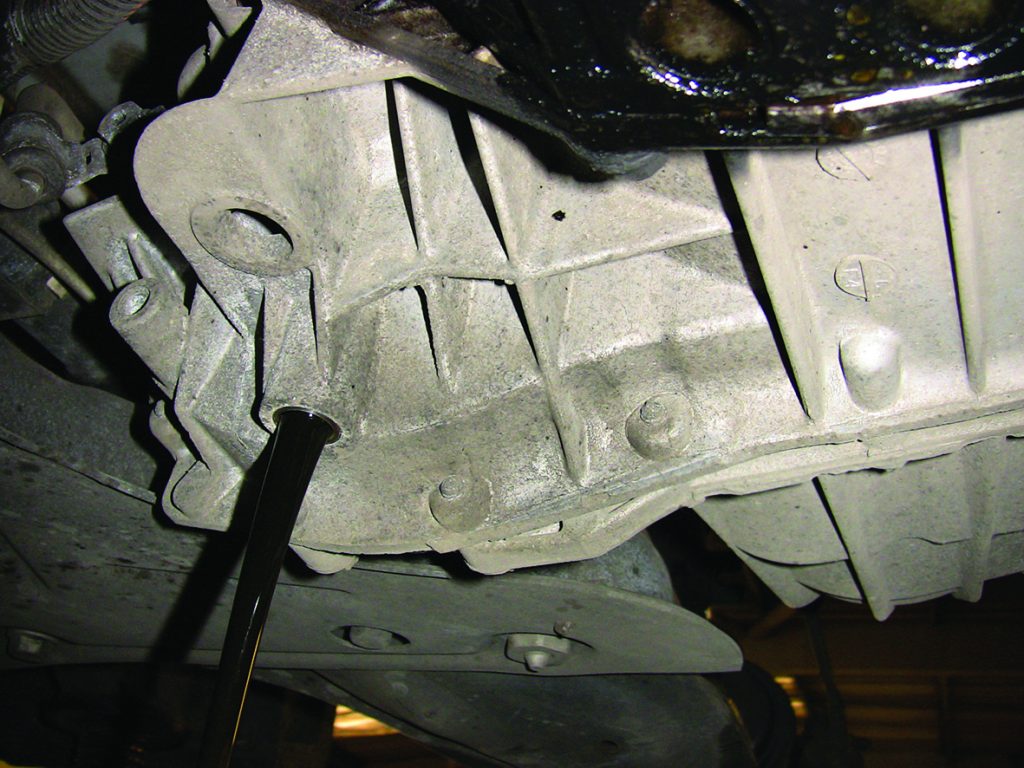
Now slacken both driveshaft/hub nuts, raise the ramp, remove the engine under tray and drain the gearbox oil (see below), lower the ramp to waist height and support the vehicle so that the front wheels are suspended.
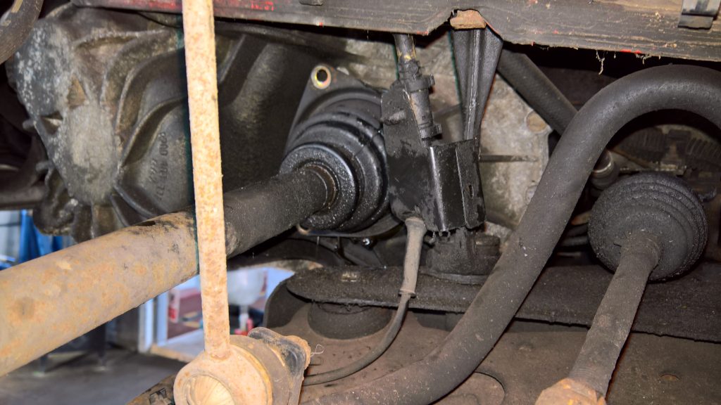
Remove both front wheels, front hub nuts and the N/S/F wheel arch liner and remove the inner driveshaft gaiter retaining bolts (see below).
Release the front flexible brake hoses from the retaining points on the front struts, remove the strut to hub assembly bolts, lever the hub assemblies out and remove the driveshafts from the hub assemblies and then remove the driveshafts from the gearbox and vehicle. Raise the ramp and remove the lower gearbox bell housing cover, then remove the starter motor bolts and bell housing bolts from behind and around the oil filter housing area (see below). These can be removed using a universal joint socket and extension tooling.
Remove the rest of the bell housing bolts leaving one accessible bolt to support the gearbox until it is removed, then remove the lower engine pendulum mounting and attach an engine support. Remove the six sub frame bolts and the four steering rack bolts, this will then allow the engine and gearbox to lower on the sub frame to aid gearbox removal.
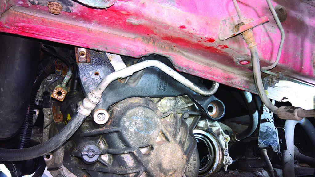
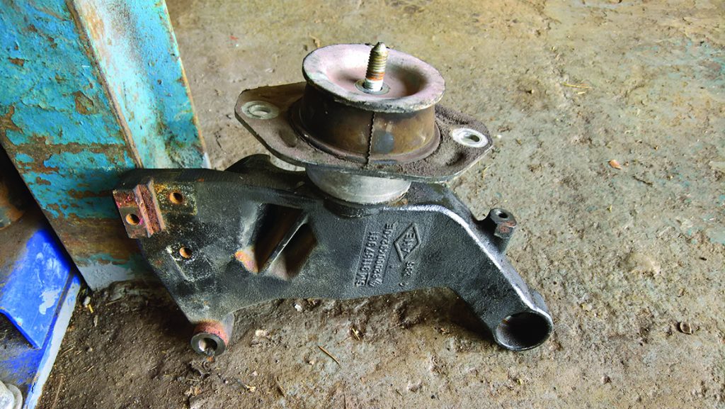
Lower the ramp and remove the gearbox mounting from the chassis leg. Lower the engine slightly on the engine support to allow access to remove the gearbox mounting, air conditioning pipe and earth strap (see below).
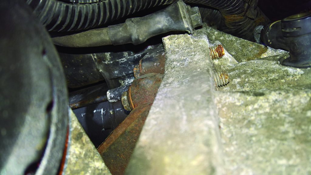
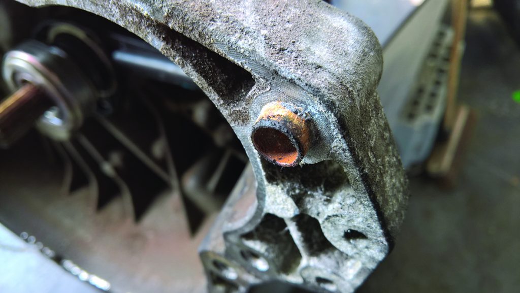
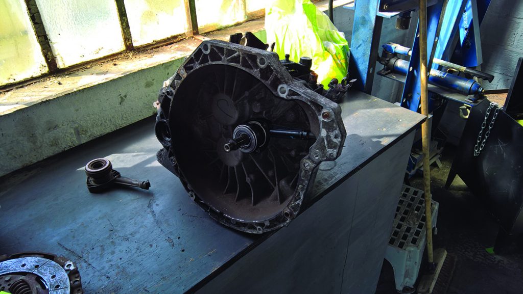
Support the gearbox with a transmission jack and remove the final accessible bell housing bolt and ease the gearbox back until it’s free and then lower to the floor. On this occasion, the gearbox had seized on the location dowels, so a little force was required to separate it from the engine (see below). With the gearbox removed, the location dowels were cleaned up with Emery cloth.
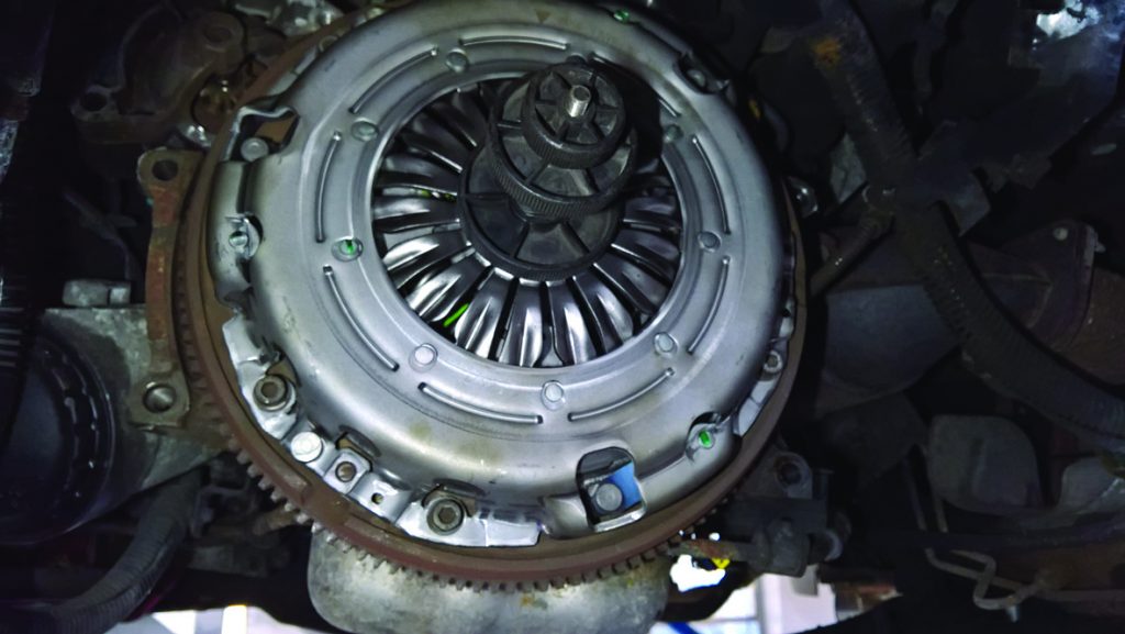
The clutch assembly can now be removed from the flywheel. Inspection found that the clutch plate had worn close to the end of its service life and the release mechanism was free from lubrication, both of which would contribute to a heavy clutch pedal. Inspect the flywheel for heat stress, such as hairline fractures or cracks. Confirm the flywheel as serviceable, remove the glaze from the flywheel face using Emery cloth and clean the flywheel and surrounding area with clutch and brake dust cleaner. Now remove the old Concentric Slave Cylinder (CSC) from the gearbox bell housing, and carry out an inspection to ensure there are no oil leaks that could contaminate the new clutch and clean the bell housing and input shaft with brake and clutch dust cleaner.
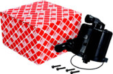
Ensure the mounting surface for the new CSC is clean and then mount it (do not ‘dry squeeze’ the CSC as this can cause damage internally or externally) and bolt into position, torqueing the bolts to the manufacturer’s specification (see below).
Lightly smear a small amount of high melting point grease to the input shaft, and then mount the new clutch plate on the input shaft which will ensure the clutch plate is correct in fitment. Evenly distribute the grease, remove the clutch plate and wipe off any excess grease. Using a clutch alignment tool, mount the new clutch on the flywheel, making sure the clutch plate is located correctly with ‘Gearbox Side’ or ‘Getriebe Seite’ facing the gearbox and tighten in an even and sequential order (see below).
At this point, it is good practice to change the clutch fluid in the hydraulic system; this will remove any contaminated fluid that could cause bleeding problems or even premature failure in the hydraulic system. This is carried out simply by allowing the fluid to flow through the system. Remembering to keep the reservoir topped up, also open the bleed valve to confirm correct operation before we commence bleeding.
The gearbox can now be installed, which is done in reverse order of removal. Torque all bolts to the manufacturer’s specification and remember to re-fill the gearbox with the correct grade and quantity of gearbox oil.
Bleeding
As mentioned earlier, the Vivaro can be ‘challenging’ when it comes to the bleeding process. The recommended process for this system is as follows and a second person is required.
Fill the clutch fluid reservoir and attach a bleed bottle to the bleed nipple. Press the clutch pedal slowly to the floor, open the bleed nipple and when the pressure has exhausted, close the bleed nipple, slowly allowing the clutch pedal to return to the start position. Then let the system rest momentarily. Repeat this process 25 times, remembering to keep the clutch fluid reservoir full. By using this method, we are allowing the clutch return system to do the work and not the pressure coming from your foot through the clutch master cylinder.


