This month OESAA members, Laser Tools and Schaeffler, have teamed up to offer advice on carrying out a ball joint replacement on a Ford Transit, to guarantee an efficient, accurate and professional job.
The evergreen Transit remains one of the most popular vans on our roads and, in the course of its duties, is subjected to arduous driving conditions – bumping up and dropping off curbs, travelling over poor roads and rough ground – so no wonder that at some point in its life, the bottom ball joints will need replacing.
The two main causes for premature wear on ball joints are primarily lack of lubrication, due to the grease leaking out or being washed out – possibly caused by damage to the protective boot – or general wear that accelerates the onset of excess free play in the joint.
Remember that any steering and suspension repairs are ‘safety critical’, so quality should be the dominant factor, not only with the parts being fitted but also with the workmanship involved.
The late-model Ford Transit bolt-in style front lower ball joints are notoriously difficult to remove – being a very tight fit, even after the securing bolts have been removed. Laser’s ball joint removal and installation tool (part number 8272) is designed to easily extract and refit this boltin type of front lower ball joint on the vehicle, removing the need to use heat, hammer blows or a workshop press.
It’s simple to use too: just remove the lower arm to ball joint nut, swing the arm out of the way, and then remove the ball joint securing bolts. Assemble the tool according to the instructions supplied, then simply wind out the bush. Installation of the new bush is just as easy.
Applications include the Transit bus (2013-onwards) and Transit platform/chassis (2014-onwards). Use it to remove and install OEM ball joints references1451917 and KT6C113K209AA. The 8272 is suitable for bolt-in type lower ball joints only. For clip type ball joints, use Laser part number 6614.
When it comes to safety-critical components, Schaeffler’s FAG steering and suspension range offers workshops a genuine quality alternative. All components are manufactured to original equipment specifications, using the highest quality materials and production standards, with everything needed for a complete repair inside the box. All metal ancillary parts are zinc flake coated to protect against corrosion, and its clear TPU (Thermo Plastic Polyurethane) boots give the strength of plastic with the flexibility of rubber, combined with the latest sealing technology. Repair instructions can be downloaded from Schaeffler’s REPXPERT information portal.
Ball joint removal:
Always refer to the vehicle manufacturer’s instructions for each specific application. It is best practice to replace both front ball joints as a pair. Support the vehicle with both front wheels off the ground and the front suspension hanging at full droop.
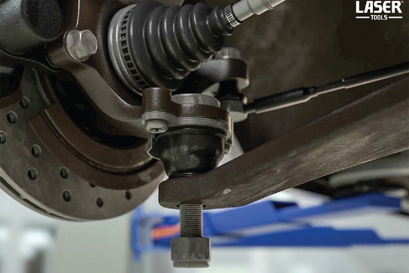
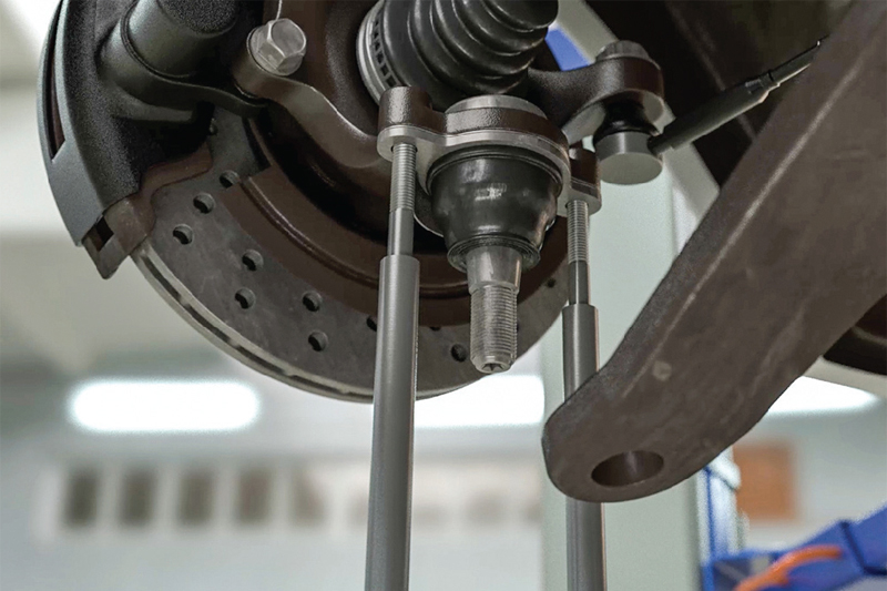
Remove front wheels. Remove the lower ball joint taper nut (figure 1).
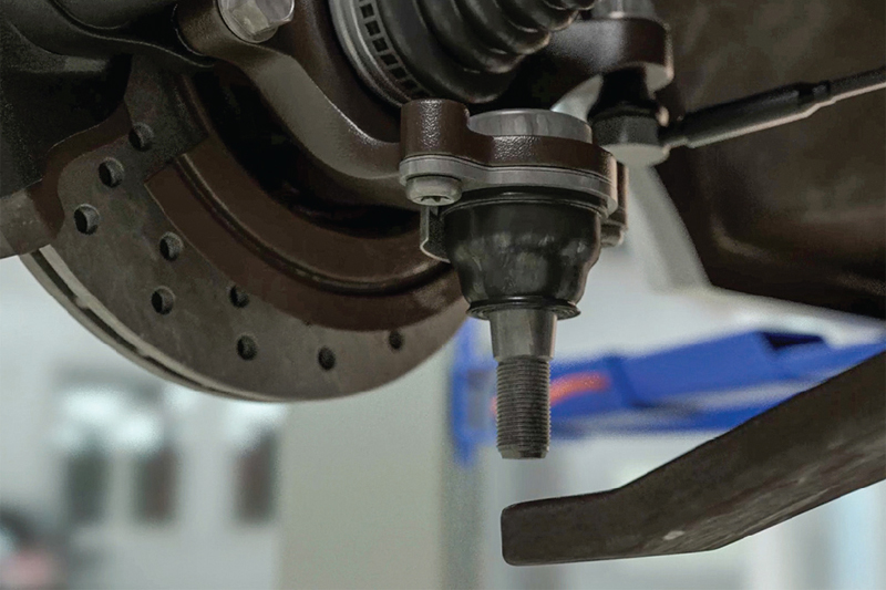
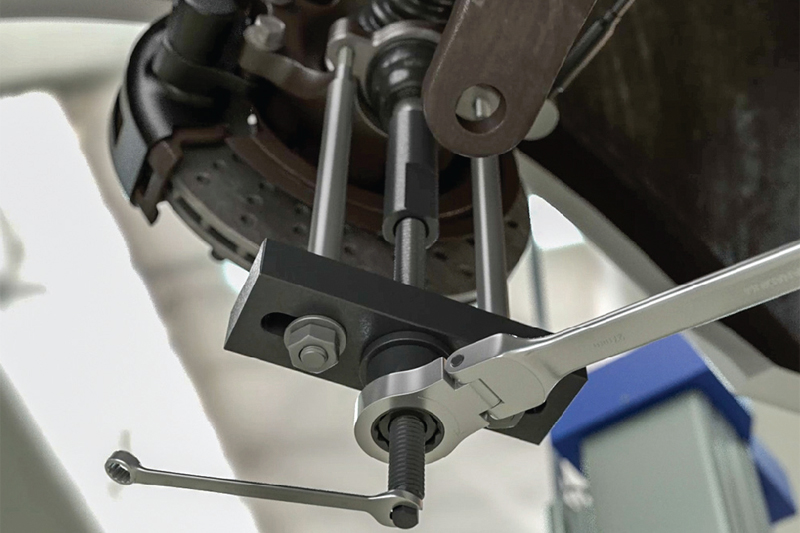
Separate the joint from the arm to access the bottom of the hub (figure 2).
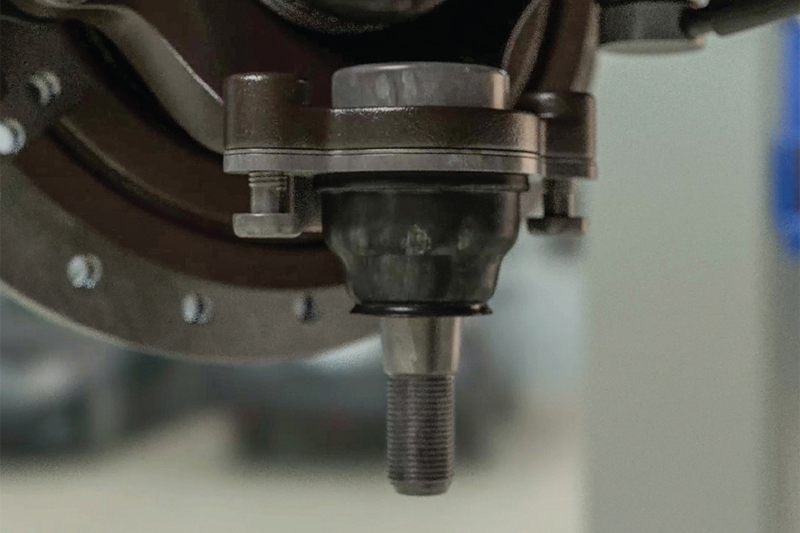
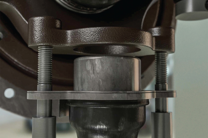
Remove the two ball joint fixing bolts from the hub (figure 3).
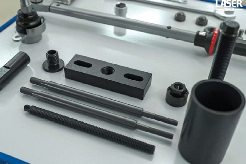
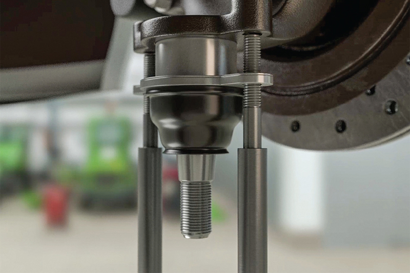
Assemble the components of the kit (figure 4) and lubricate the main force screw with molybdenum disulphide grease. Ensure that the support rods are screwed in fully (figure 5).
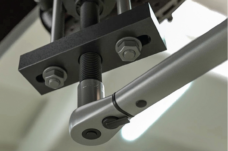
Check that the joint adaptor has been fully screwed onto the ball joint taper thread. Likewise that the top plate threaded adaptor and the support rod nuts and washers are all correctly tightened. Start to pull the ball joint out by turning the bearing nut, while holding the force screw steady (figure 6).
Continue turning until the ball joint is fully removed (figure 7).
Ball joint installation:
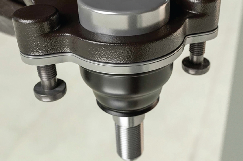
Remove the extraction assembly and reassemble the 8272 press-frame using the installation force screw. Lubricate the force screw with molybdenum disulphide grease. Place the new ball joint in position then refit the support rods to the hub (figure 8).
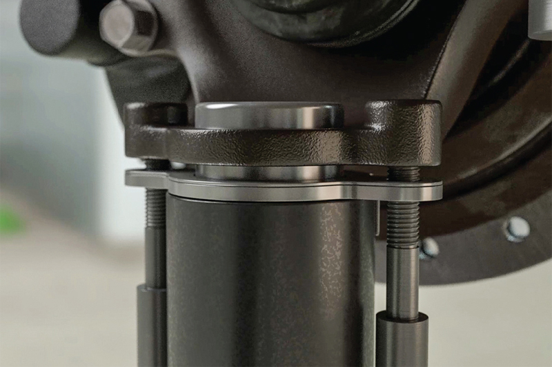
Fit the insertion cup over the joint, then assemble the top plate to the support rods and force screw. Check the support rods are evenly tightened and the top plate is level to the hub face (figure 9).
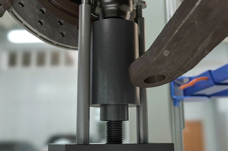
Steadily press the joint in to place by tightening the force screw (figures 10 and 11).
When the ball joint is fully inserted, refit the fixing bolts (figure 12).
Refitting of removed suspension components can then be carried out in reverse order of removal. Remember to torque up all bolts to the manufacturer’s specification, and it is always recommended to carry out a wheel alignment after work has been carried out on the steering and suspension.