In the first of a two part series, Pico technician Ben Martins gives the new 8-channel PicoScope 4823 a road test when looking at a DAF rear steering fault.
Hydraulics really isn’t something that you just have a go at. I think we all take for granted the risks we take in our chosen career and forget how dangerous this job can be. Hydraulic systems are especially risky. They work at high pressures, generating high temperatures, and without the appropriate training, you will put yourself, unnecessarily, in harm’s way. If you are working with hydraulics already, then hopefully this will make you think differently about how you can diagnose and record faults.
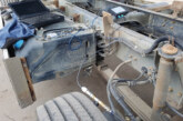
I was asked by a customer if I was interested in taking a look at a problem dust cart. The owners, in the attempt to get a silver bullet fix, requested a part replacement based on a limited diagnosis. The part was reluctantly replaced by our customer, but, as you’ve probably already guessed, it didn’t fix the problem. We were determined to do it properly, to find the fault, prove it and then verify the fix with PicoScope.
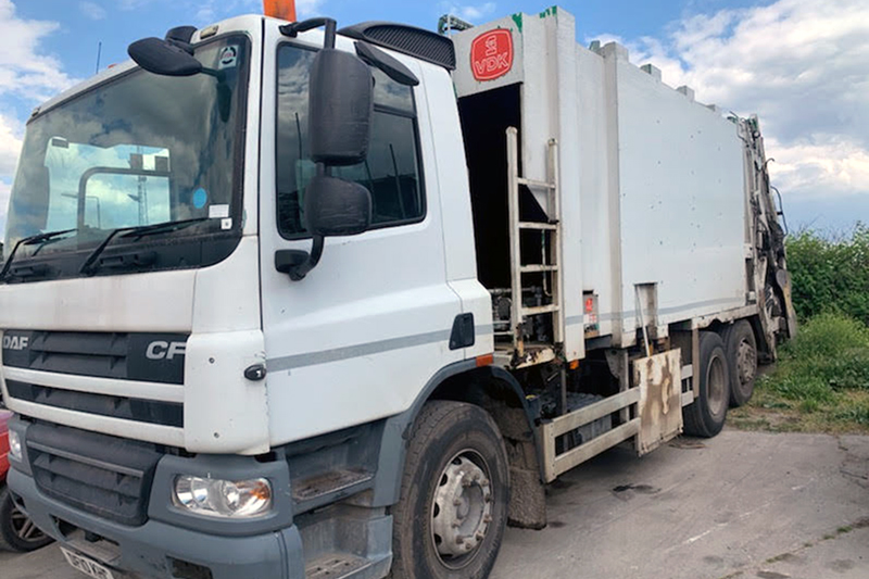
As always, we had to begin by confirming the customer’s complaint. On many long wheel-based trucks, the rear axle should steer during slow manoeuvring to decrease the turning circle and improve manoeuvrability. In this case, the rear steer would begin to work, but after a short time of operation, it would put a warning light on the dash, and the rear steering axle would self-centre and no longer operate as intended. If the vehicle was switched off, left and then restarted, operation of the rear steer would resume, only for the fault to be set again.
It was easy to confirm the fault, and with the light on the dash, I recovered the DTCs, which displayed the following:
- 600-17: Centring Pressure Sensor value too low and there is a leakage
- 600-1: Centring Pressure Sensor value too low; dangerous
- 630-31: Centring Pressure Loss, pressure drop too high within three seconds
We made sure that the codes were permanent by clearing them and then operating the steering again. Not only did this help to confirm that the codes were still active, but it also helped to repeat the test to make sure that the vehicle set the fault. This is vital when it comes to verifying the fix.
We now had a clear direction with where to go next, which was to look at the rear axle centring pressure.
Understanding how the system operates and functions is important to be able to create a good action plan and, ultimately, to fix the fault. The system fell under the heading of E-MAS, which stands for Electronically controlled Multi Axis Steering system. TRW Automotive designed steering systems for more than one company, so I’d expect that it can probably be found on more than one manufacturer’s vehicle.
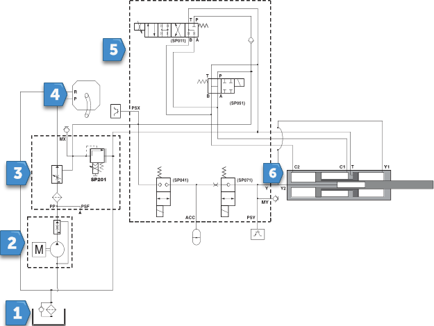
Luckily, the customer I was supporting had access to the DAF technical site. Although all of DAF’s diagrams are chassis specific, they also depend on the date and time the schematic was downloaded. This is because they update their technical data daily. It is good practice to make sure you have the correct variant of vehicle, as having the wrong information could send you off in a completely different direction. This isn’t a lesson in hydraulic drawings, but there are a couple of things that we need to be aware of.
The first is the relief valve labelled in the diagram as SP201 in the front valve block. This is a vital safety element of any hydraulic system to prevent catastrophic damage due to the high oil pressures that are created. According to the information we have found, the maximum working pressure is 175 + 5 bar, and the relief valve ensures that if the pressure gets above this, it will open and allow the oil to flow safely back to the reservoir without destroying the components of the circuit. This relief valve is also operated by a solenoid, which, when activated, prevents it from opening so the maximum working pressure can be created. Remember, with any hydraulic system, pressure isn’t created by the pump; pressure is resistance to flow much like how oil pressure is created by the crankshaft in a combustion engine.
The next safety valve on this system is located in the rear valve block and is tagged as SP051. In its ‘not active’ state, it allows the oil to flow directly from the pump and return to the tank with no restriction, and therefore no pressure is generated. It also connects both sides of the cylinder to drain back to the tank to allow easy movement of the cylinder. When this valve and the relief valve are activated, the oil has no easy path back to the tank, which causes the pressure to rise until it meets the mechanical limit of the relief valve. This ‘pushing’ force is what will move the cylinder to turn the wheels.
While we’re talking about safety, this system has a self-centring fail safe built into the cylinder, which, in the event of a malfunction, will force the cylinder back to the centre and straighten the wheels. Knowing how this works is important, as the fault is caused by the centring pressure being too low.
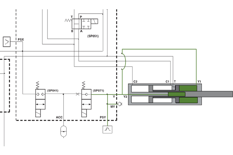
The ‘floating end plate’ part of the centring system will mechanically lock against the stops in the housing, and the smaller section will provide a stopping point for the main rod. This gives the steering cylinder its central position. When the centring system is activated due to a fault, or if the vehicle travels above a set speed, SP071 deactivates first, preventing oil from travelling back to the accumulator. However, due to the one-way valve, the accumulator can still supply pressure to the centring circuit. The SP051 solenoid deactivates next, giving the C1 and C2 ports on the cylinder an easy path back to the tank. Because the pressure is now much lower, the centring system pressure can take over and force everything back to centre. As the surface area of the chamber, Y1 is twice the size of Y2, and with more force applied in this direction, the floating piston will always travel back this way. Once the end plate is in position, Y2 will continue to force the main rod onto the other end of the floating piston, making the wheels centre. Once in position, the one-way valve prevents any movement of oil and therefore hydraulically locks the cylinder.
The accumulator relief/loading valve, SP041, is there to manage the pressure in the centring circuit, and to try and maintain a consistent nominal pressure of 28 bar. If the pressure deviates too much from this, the valve can be opened to either drop or increase the pressure. Fluctuations here are normal due to oil temperature and valve operation, but the pressure should be stable and constantly applied to the centring circuit even when the vehicle is stopped.
The last thing before getting into the measurements is to understand the accumulator, a storage device that acts in a similar way to a capacitor. It has the ability to store and release energy depending on the component requiring it. These spherical devices are extremely dangerous and shouldn’t be touched if you don’t have appropriate training or tools. They contain a chamber that stores nitrogen under high pressure and supports the hydraulic pump, so if the demand is high, it can add to the system. Equally, it can absorb large spikes of pressure. If you’ve never dealt with these and have one in the workshop, please don’t just take your spanners to it.
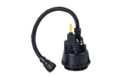
Having dealt with safety issues and understanding how the system should function, we could now set out our diagnostic process. We had verified the fault and confirmed with the customer that this was the problem. After we retrieved faults relating to the centring steering pressure, we now had an understanding of how the system should operate under normal conditions. Having eight channels meant we had a lot more freedom to choose signals to capture, but we needed some form of input to know that the steering was being operated. The front and rear axle angle sensors would be useful, and we also wanted to see the pressure at the front valve block and in the centring system. I also wanted to see what the solenoids were doing, and so I had something to reference later on, I also captured engine speed to prove the engine was actually running. With the new 8-channel scope, I had the option to capture multiple signals simultaneously, and my initial setup was as follows:
- Ch A – Optical pick up for RPM signal, can be converted to a math channel to visualise RPM
- Ch B – Front Valve Block Test Port WPS600
- Ch C – Rear Valve Block Test Port WPS600
- Ch D – Current to SP051 Release Valve Solenoid
- Ch E – Current to SP201 DRV pressure from front valve block
- Ch F – Front Steering Angle Sensor
- Ch G – Rear Steering Angle Sensor
- Ch H – Current to SP071 Accumulator Solenoid