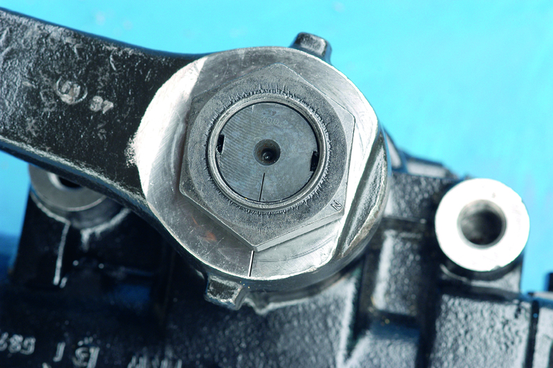
Fig. 1
Under its TRW brand, ZF Aftermarket offers a comprehensive service manual for its TAS and THP integral steering gears, including how to diagnose a steering problem without physically removing the steering gear. Here, the business looks at how to determine what the problem might be if a vehicle containing this component requires servicing.
The THP power steering gear series is the latest design in the family of integral hydraulic power steering gears. Integral hydraulic power steering means that the gear box contains a manual steering mechanism, a hydraulic control valve, and a hydraulic power cylinder, all in a single, compact package.
Preliminary checks
To diagnose a steering problem, ask the right questions: If the vehicle’s hard to steer, find out exactly what this means. Is it hard steering into a right or left turn? Is the problem only while the vehicle is sitting still? Is there only intermittent power steering? Or is there no power assist at all?
If possible, and if it is safe to do so, test drive the vehicle. If you are not familiar with the rig, allow the customer to drive it while you sit beside them. Take hold of the wheel while they drive to get a feel for the problem they are concerned about, and arrange for a load to best replicate the day-to-day demands on the vehicle. Before you take out a steering gear, first look at what else could be causing the problem.
► Check the tyre pressure and that it is equal all around, properly sized, and not worn or damaged.
► Check the front end alignment and look for abnormal looseness or tightness in the steering linkage, ball joints, and kingpins.
► A service replacement hose or fluid line may be misrouted or may be too small in diameter, or may be restricted in some other way. Replace any hose that is kinked or bent sharply. Replace any hoses that are not the same as the original equipment.
► Check the power steering fluid reservoir to make sure that oil is up to the correct level.
► Check the pump drive belt, if one is used, to see if it is slipping. The belt may be tight, but it may also be glazed, and a slipping belt doesn’t always squeal. If you adjust the belt, check the specifications.
Hydraulic tests
If the checks described above all prove satisfactory, it is possible that the cause of the steering problem can be traced to a lack of pressure or insufficient flow. In this case, you may have to do more detailed troubleshooting that involves conducting hydraulic tests.
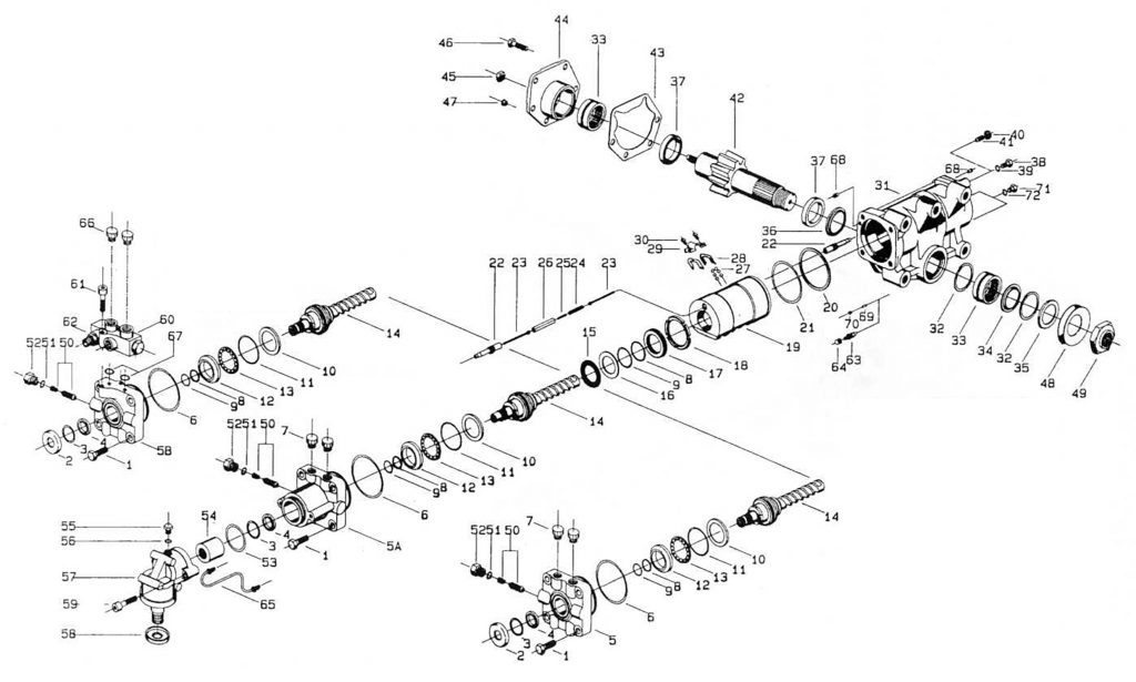
Adjustments on vehicle
All numbers in the brackets refer to the exploded view image.
When you have conducted these checks and tests, you may find it necessary to adjust the steering gear. There are two adjustments to be made to the steering gear while it is installed on a vehicle.
One is the sector shaft adjustment, and only if the shaft adjusting screw and jam nut (45) are accessible. A manual poppet adjustment is possible after initial poppet valve adjustment at installation. If the steering gear has a fixed stop screw (38) and washer (39), you must replace them with a special service poppet adjusting screw (41) and sealing nut (40) to make this adjustment.
Some of the photographs in this section show a gear mounted on a mock-up frame for clear illustration. Worm preload was achieved during assembly of the steering gear. If axial lash (movement) of input shaft is evident during a steering manoeuvre, the steering gear must be disassembled and repaired.
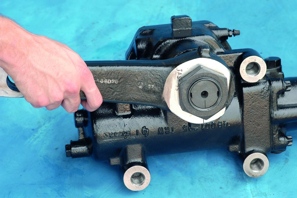
Sector-shaft adjustment
1. Locate adjusting nut: If the sector-shaft adjusting screw jam nut (45), located on the side cover, is not accessible, the steering gear must be removed prior to adjustment.
2. Centre the sector shaft: To position the sector shaft (42) on centre of travel for this adjustment, rotate steering wheel (input shaft, valve worm assembly) until the timing mark across the end of the sector shaft is perpendicular to the input shaft, valve worm assembly and in line timing mark on the end of housing (31) trunnion (Fig. 1 – see above). This adjustment must be performed with the sector shaft on its centre of travel.
3. Remove the drag link: If the sector shaft adjusting screw is accessible for adjustment, remove the drag link from the pitman arm (Fig. 2). The input shaft, valve worm assembly (14), must not be rotated more than 1-1/4 revolutions from the centre of travel while the drag link is detached from the steering gear to avoid possible maladjustment of the poppet system.
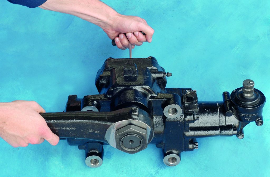
4. Check for lash: With the sector shaft (42) in the centre position, grasp the pitman arm and gently try to move this arm back and forth in the direction of travel. Fingertip force is adequate to detect lash of loose sector shaft. There must not be movement of the input shaft or sector shaft (Fig. 2).
5. Position adjusting screw: Loosen jam nut (45). If no lash was detected, turn shaft adjusting screw counter clockwise until lash is detected.
6. Adjust shaft: To adjust, slowly turn the shaft adjusting screw clockwise until no lash is felt at the pitman arm – use no more than 14Nm of torque. From this no lash position, turn the screw clockwise an additional 1/8 to 1/4 of a turn. Hold the adjusting screw in place, and tighten the jam nut (45) (Fig. 3).
Final torque: as per torque chart. Over adjustment of shaft adjusting screw clockwise could induce a no recovery, over-steering or darting condition in the vehicle!
7. Recheck for lash: Recheck the pitman arm for lash. Turn the steering wheel 1/4 turn each side of centre. No lash should be felt. If lash exists, repeat steps 5-7.
8. Connect drag link: Reconnect drag link to pitman arm.

