Picking up from where he left off in last month’s issue, Pico technician Ben Martins continues this overview of the new 8-channel PicoScope 4823, which he tested when overseeing a DAF rear steering fault. Not only did Ben have eight channels to play with, he also had the opportunity to put Pico’s WPS600C Hydraulic Pressure Transducers to work.
As the fault only occurred after some time had passed, I was going to be looking at a relatively slow time base. Switching to streaming mode dropped the sample rate and limited the number of buffers to one. From here, I was able to capture the fault, and then use the zoom and filtering tools to help highlight the areas of concern in greater detail.
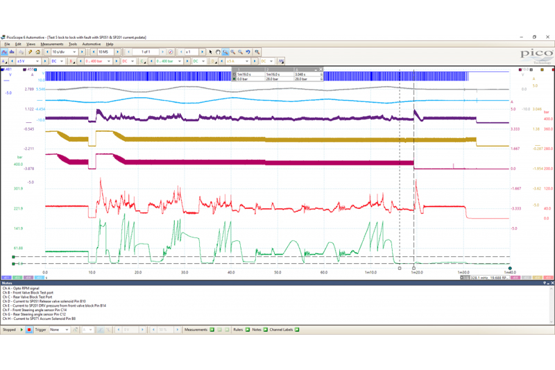
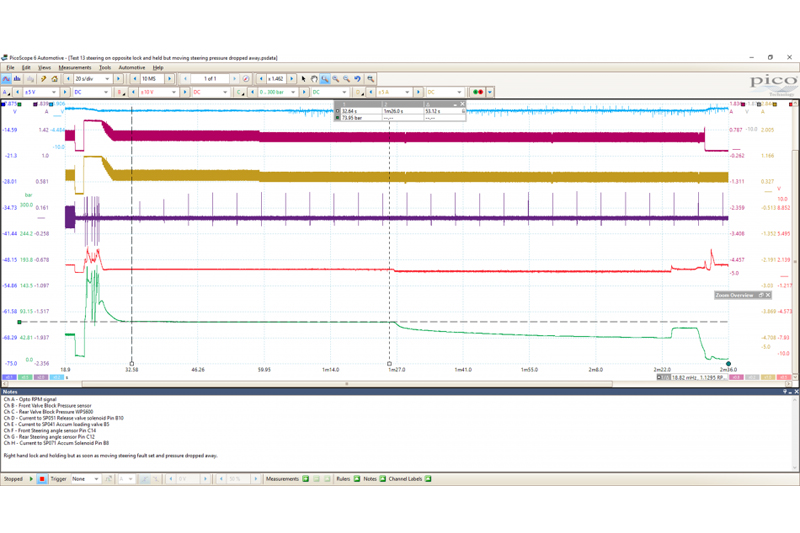
From the screenshot, we can see that as the steering started to turn and SP201 was activated to allow the pressure to increase, the accumulator solenoid, SP071, was activated to allow the oil to pass to the safety circuit, freeing the cylinder and allowing movement. SP051 was also activated, preventing the flow of oil to return to the tank easily, meaning we could use the oil flow to do ‘work’ and steer the rear axle. During the movement of the rear axle, we noted that the operation wasn’t smooth; if something would catch, it would then release. There was also a noise that occurred, which sounded like the release of pressure or a change in a valve. The noise occurred at the same time as the peaks in the centring circuit pressure. Could this be the first clue of the puzzle?
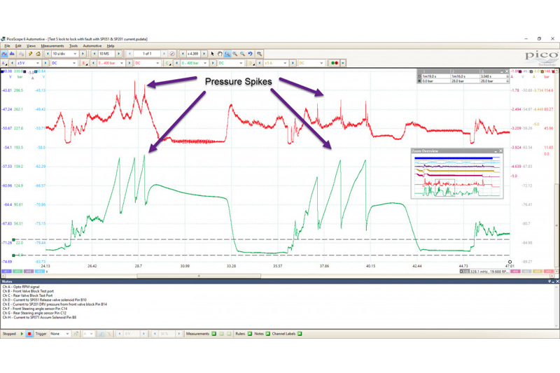
The left-hand time ruler was positioned just as the warning light in the cab came on, which tells us that something happened, and by using an additional time ruler, we can see that three seconds lapsed with the pressure measured at zero. The pressure in the centring circuit was meant to be maintained at 28 BAR. I’ve added a vertical ruler at this figure, and we can clearly see that it is much higher than this, and peaks at around 180 BAR. One interesting note was that the accumulator valve was switched off with the fault, and we got a command for an increase in steering pressure, which is seen on Channel B.
Important things to note from this capture:
- The pressure is being commanded and increased by SP201 as expected
- The accumulator solenoid is being activated during steering, but shut off once the fault and DTC triggered
- SP051 is being commanded during steering as expected
- Both angle sensors are changing in connection with steering input from the driver
- System pressure appears good with no excessive spikes other than after fault
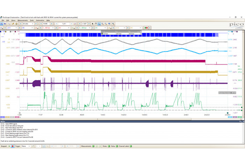
 I believed that the supply of oil was good and that the pressure represented the command from the SP201 valve. We felt that we didn’t need to look towards the front valve block, and by swapping the current clamp to SP041, we could see how this valve was interacting with the centring circuit pressure. On top of this, every time there was a pressure increase in the centring circuit, there was a small pressure spike in the steering circuit. The only way these two circuits can interact is via the SP041 valve, which is there to supply or discharge the centring circuit pressure.
From the capture above, we can see that the SP041 plays a part during the pressure increase in the centring circuit, and if we zoom in around this, we can view it in more detail.
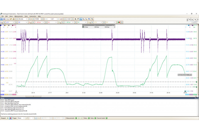
It’s clear that every time we saw a pressure spike, the SP041 solenoid was activated and the pressure dropped rapidly. However, the only place it could go was back into the system pressure. Knowing that the system pressure was lower around the same time as the spike, it would make sense that the spike we see in the system pressure came from the centring pressure circuit. We could also see the solenoid being activated at various points during this capture, not just at the spikes.
Covering all bases
The EMAS ECU was monitoring pressure, the question was: where does the pressure go when the fault occurs? We knew from the technical information that the pressure should be constant, but we had varying fluctuations from 0 to 178 BAR. Happy that the system was responding electrically to what it saw, the only other components left were the accumulator and the steering cylinder.
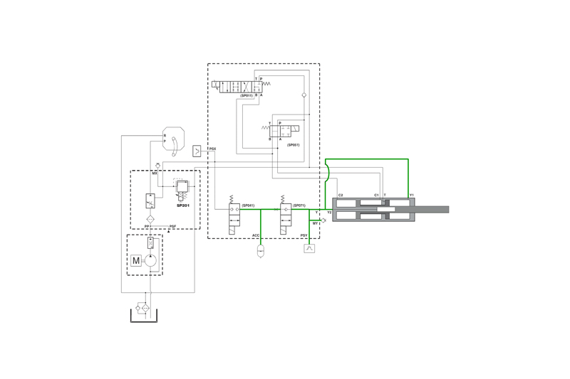
 At this point, you could make a call and just replace the cheapest option, or we could try and work out if there was a way for us to verify the failing part. Going back to our earlier drawing of the cylinder, we could see that there was a path back to the tank for the oil. Inevitably, hydraulic circuits are never completely sealed, and there will always be some leakage across seals. What if the seal between the floating cylinder and the tank line was leaking? Would this cause a significant pressure loss to cause the fault? And how can we prove it?
Looking at the cylinder, we decided that we could manoeuvre the cylinder all the way out. This would leave a large void behind the endplate of the floating cylinder. If we could maintain a pressure in the centring circuit by holding on a hard lock, and we saw no activation from the SP041 to relieve pressure, then we would be satisfied that it wasn’t leaking excessively over this area.

As we can see, we held a steady pressure for around 53 seconds while holding on a full lock. When we released the steering wheel without turning, the pressure started to fall away slightly. However, this happened nowhere near as rapidly as before, and it certainly didn’t drop low enough to trigger the fault code. Seeing this, I felt there was enough evidence to prove that the cylinder in this instance wasn’t leaking internally, as we were happy that the pressure dropping away in the centring circuit was not down to a cylinder leak. Sometimes, proving what isn’t faulty is as important as proving what is.
Finally, only the accumulator remained, but how could this be the cause of the fault? The accumulator takes on pressure and then releases it, as the system requires it to maintain a constant pressure. Why didn’t we just replace it earlier? That would have meant opening the hydraulic lines and risk contaminating the system for the sake of a guess.
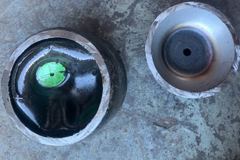
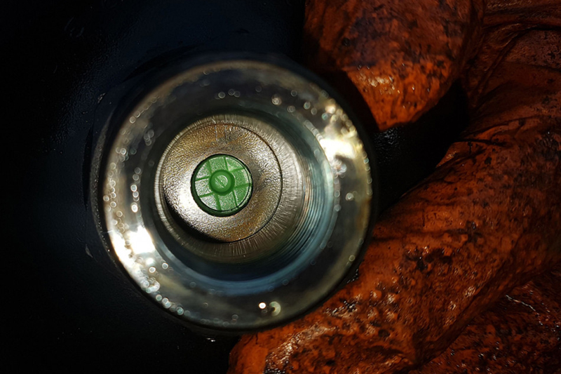
Removing an accumulator, for example, should only be done when you are 100% certain there is no pressure in the circuit. We had seen the centring pressure reach 178 BAR at times, so we had to be absolutely confident that it had been discharged first. Once it was removed and compared to a new one, it was clear that we did indeed have a faulty accumulator.
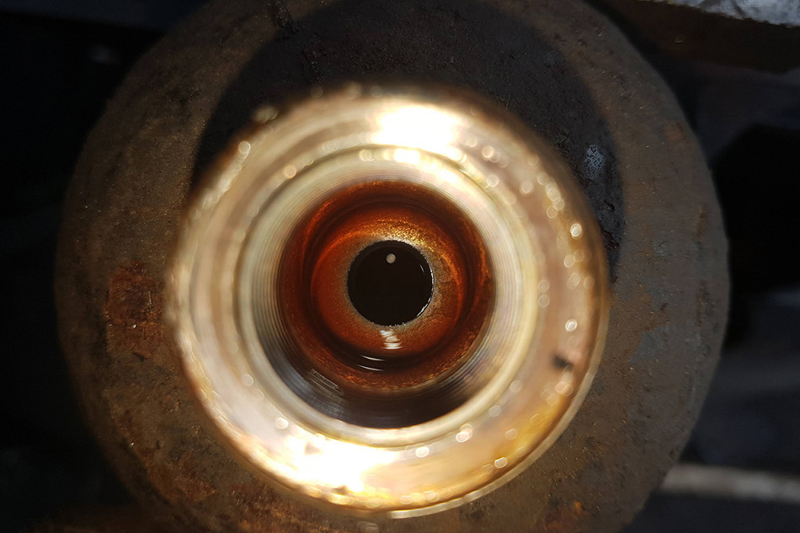
The green valve you can see in the new unit indicates that the bladder is fully inflated, whereas it is nowhere to be seen in the old one. A borescope revealed that the bladder was completely deflated and the valve was positioned near the bottom. There was only one thing left to do then; refit the accumulator, making sure that everything is tightened to the correct specifications, and bleed the system. Using dealer equipment meant we had access to the air bleed option that instructed the EMAS to purge any air from the system. Once this was complete, and after a quick check for leaks, we could carry out the verification.
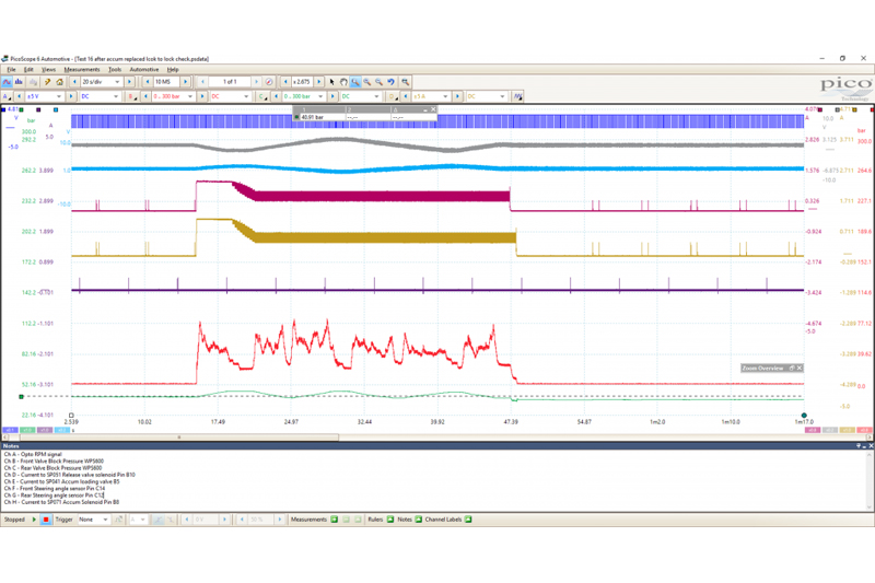
As you can see from the capture above, we completely lost all the spikes from the centring pressure when we were operating the steering. SP041 was no longer having to be activated to remove any excessive pressure or be opened to allow pressure back in to compensate for a pressure drop. The centring pressure sits very smoothly at around 40 BAR, which may settle further considering that the technical information we have found states it should be maintained at around 28 BAR. However, the pressure was maintained after the steering manoeuvre had finished. Even when the system pressure dropped considerably, we still had pressure in the centring circuit, which wasn’t happening prior to the accumulator being replaced. The vehicle has now been road-tested and no further faults have been reported.
This case study shouldn’t be used as a training guide to hydraulics. What it can do is highlight the possibilities that are now available to a technician when you can view more than four measurements simultaneously. Of course, an 8-channel scope brings its own challenges, but when multiple measurements need to be made, it saves essential time. Being able to see the interaction between sensors and actuators can really help technicians understand how a system works.