Wayne McCluskey is the Technical Training Manager at ZF Aftermarket, which supplies the automotive aftermarket with Lemförder and TRW steering components. Here, he reviews some indications that attention to the steering system is needed and provides a checklist of items that deserve close examination.
For technicians servicing commercial vehicles on a daily basis, identifying and rectifying potential safety defects is a routine but vital part of the job to ensure that a vehicle will pass a DVSA annual inspection or fleet compliance check. Exposed to the elements, the joints and linkages within the safety-critical steering assembly are prime candidates for wear and damage in service. Here is how technicians should approach steering system examination.
Vehicle behaviour suggesting remedial action is required
Road wander requires the driver to continually compensate for changes in vehicle direction that occur independently of driver input. This can be caused by worn or loose components in the steering linkage, where track rods, drag links, pitman arms and steering gears move randomly within any clearance that has developed.
Wheel shimmy can also be caused by worn linkages. Ongoing oscillations in the steer axle can cause vibrations in the steering wheel, and the steering may also take longer to return to centre.
Oversteering – or ‘darting’ – manifests itself as a delayed reaction to the steering wheel being turned. Even carrying out a simple manoeuvre like changing lanes can become a challenge for the driver, who turns the steering wheel to little or no response from the vehicle, so applies additional lock. The vehicle suddenly responds to this exaggerated movement by darting across the road. Darting is typically due to a partial seizure somewhere in the steering system.
Preparation and precautions
Prior to inspection, clean all joints and mating parts of the steering linkage with dry rags (no solvents), being careful not to damage sealing boots. Any components found to be in unsatisfactory condition during the following procedures should be considered for replacement. After dismantling, always replace mounting hardware such as bolts, nuts, and cotter pins, etc. Do not weld, heat or forcibly align components. Observe the vehicle manufacturer’s tightening torques for fastenings. Unless otherwise stated, carry out the following operations with the weight of the vehicle on the wheels.
Drag link and tie rod
- Inspect the hollow tube of the tie rod or the drag link adjuster for deformation – for example, crushing by vice grips.
- While an assistant turns the steering wheel from lock to lock, feel for movement between the threaded part of the tie rod and its tube or adjustment sleeve. Any play here suggests the thread is damaged, so replace one or both of the components.
- Check the condition of the clamp and pinch bolt – the bolt must be straight, and both bolt head and nut must bear tightly on the clamp. Pitting due to corrosion on the bolt, nut or clamp should be no deeper than 0.5mm. If any of these criteria are not met, replace the affected component.
- When reassembling, adjust the tie rod length either by turning the connecting rod or the adjusting sleeve. Adjust the length of the drag link such that it can be inserted in the steering lever or steering column without tension.
Ball joint
- Inspect the housing, shaft and end cap of the ball point, paying special attention to crimped edges and end cap walls. Pitting or corrosion should be no deeper than 1.0mm.
- Inspect the sealing boot surface for holes or cracks. Apply sufficient hand pressure to distort the boot – a negligible seepage of grease at its opening is permissible but there should be none elsewhere. Any damage to the sealing boot indicates that replacement of the joint is required, as water entering the joint can lead to imminent failure.
- Check that clamping and retaining rings are present, undamaged, and correctly pressing the sealing boot against the housing and/or stud.
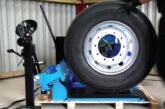
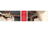
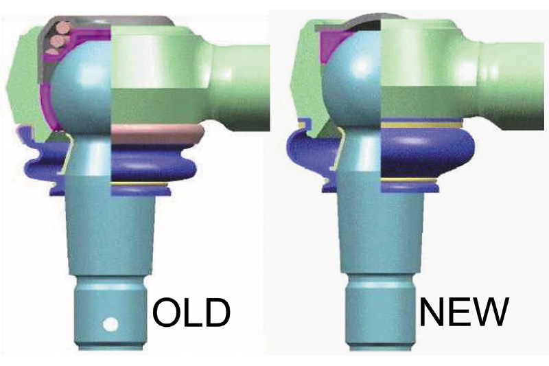
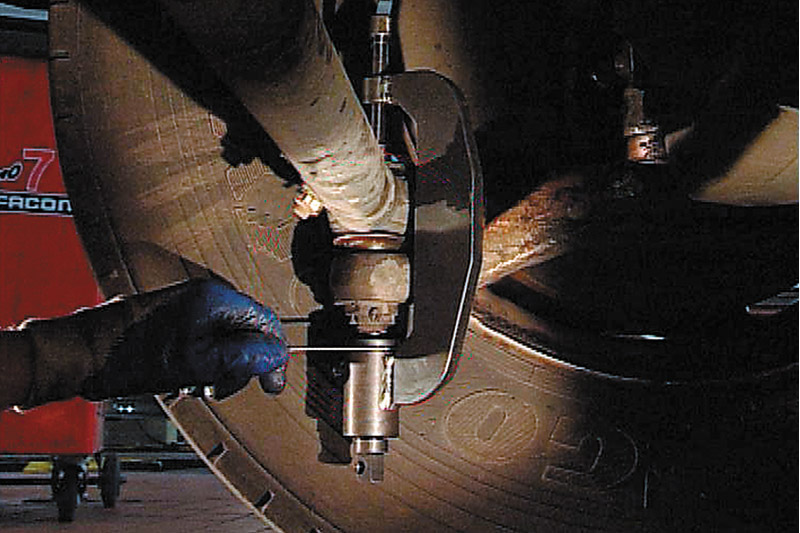
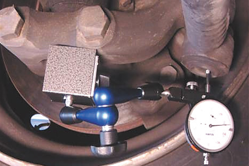
- Measure the axial play of the ball joint. Two types of Lemförder ball joint are typically found in the vehicle parc; an older version with a flat sealing cap and the current version with a domed sealing cap (Fig 1). A spring provides preload in the old type, whereas the latter type is preloaded by a profiled rubber O-ring. To measure wear in the earlier design of ball joint, use Lemförder testing tool LMI 27351.01, following the directions supplied with it (Fig 2). The current design of Lemförder ball joints cannot be accurately tested with this tool; instead, use a dial gauge mounted on a stand with a magnetic base to measure the axial clearance of the ball joint (Fig 3).
- If a defect is identified in any component of a ball joint (e.g. the cup seal or ball pin), replace the entire joint.
Torque rod and triangular torque rod
- Check for play between the torque rod bracket or bush and mounting points.
- Inspect the metal parts of the bush for cracks or other damage/deformation.
- Check that the fixing bolts are not loose, broken or missing.
- Check for missing, broken or incorrectly seated circlips.
- Inspect the torque rod bracket for fractures, or cracks that could develop into a fracture.
- Note the number of compensating discs when removing a torque rod, and relocate them in the same position during reassembly. Replace any damaged compensating discs. Torque rods must be replaced in pairs.
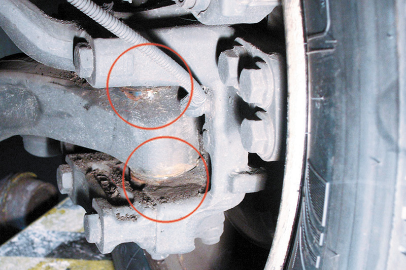
King pin
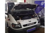
- Raise the front of the vehicle to unload the steering axle, and then check for excessive axial play between the steering knuckle and the body of the front axle (Fig 4).
- Check for stiffness in the steering return or failure to return perfectly to the straight-ahead position.
- If either condition is evident, replace the king pin and its bearing components. Incorporating these inspection elements into the routine maintenance schedule not only provides reassurance for the vehicle operator, but is also a useful additional income stream for the workshop.
Incorporating these inspection elements into the routine maintenance schedule not only provides reassurance for the vehicle operator, but is also a useful additional income stream for the workshop.