MEI urges technicians to consider the following points if the whole caliper needs to be replaced.
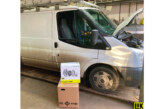
First of all, it is important to be clear on the reason why a caliper needs changing. Failure to recognise the root cause can result in a new caliper having problems soon after instalment, for example, water ingress through the air chamber, as shown in CVW’s October issue. Identifying which replacement caliper you need is also a key issue. If the original part number is still visible, then cross reference is easy. If not, you can refer to ‘ADB Identification’ on the MEI website.
When changing a caliper, the whole brake assembly is normally removed. On some vehicles, typically trailer applications where access to guide sleeve bolts is not restricted, it may be possible to leave the carrier in place.
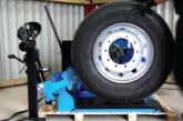
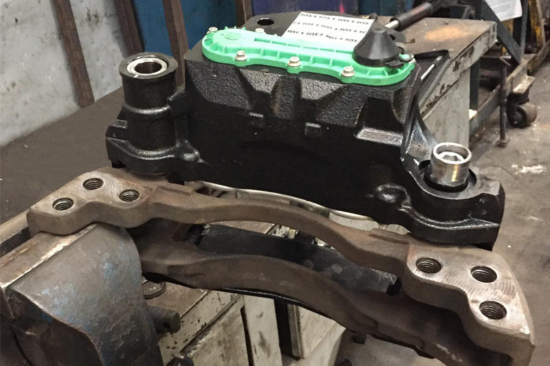
If the whole caliper assembly has to be removed, it is important to remember that when loosening (and tightening) the guide sleeve bolts, the carrier must be held securely at the same end as the bolt you are releasing (Fig.1 & 2).
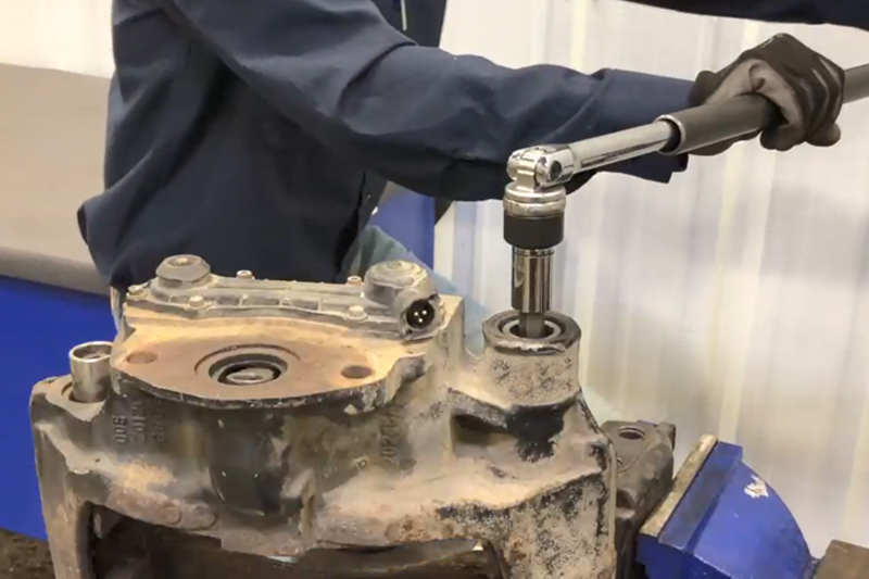
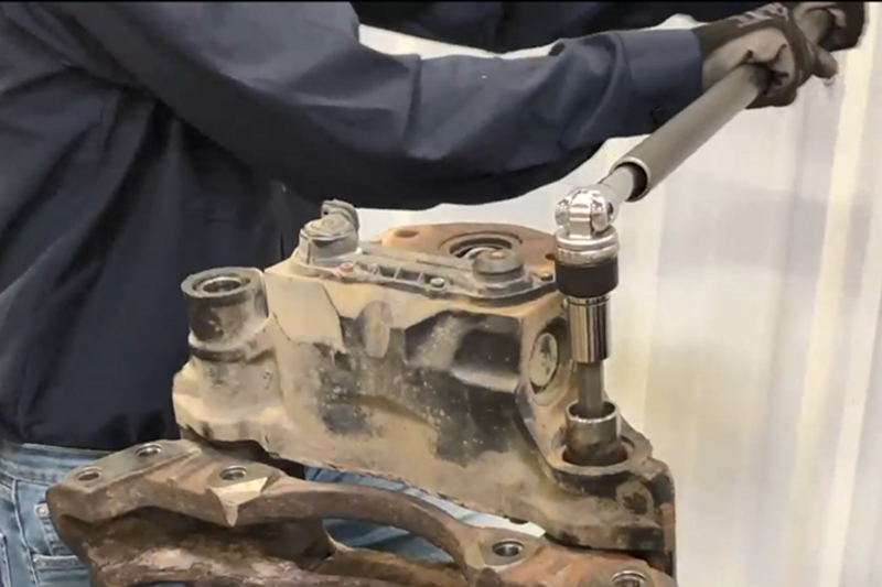
Failure to hold the carrier can result in a bent or even broken carrier, due to the forces needed to release (and tighten) the bolts. If you have sufficient access to do this on the vehicle, the brake mounting bolts do a good job of protecting the carrier.
With the caliper removed the carrier can now be inspected. The pads can make indentations in the carrier abutments and corrosion can also get a hold. This can result in sticking pads which can cause dragging or taper wear. Clean the abutments as shown in Fig.3 & 4 (use file or similar) and if indentations remain, it may be necessary to replace the carrier.
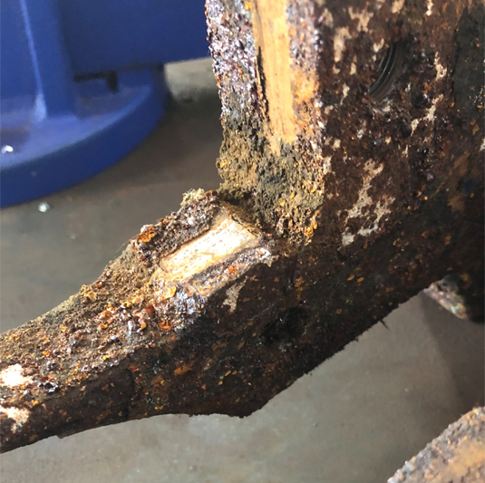
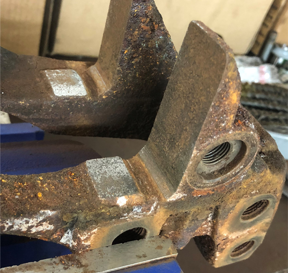
The carrier shown had sticking pads but cleaned up well. Ensure the guide sleeve counter bores and threads are also clean and free from corrosion/damage.
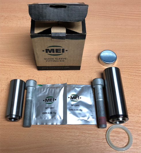
New calipers come with a complete fitting kit (Fig.5). The correct grease is important as alternatives can affect sliding, or may not have the correct thermal properties. The same applies to bolts. Use the new ones supplied and ensure they are tightened to 180Nm, plus 90°. This high torque ensures the bolts stay tight in all conditions. New bolts are needed as it is not recommended to tighten more than once to this level.
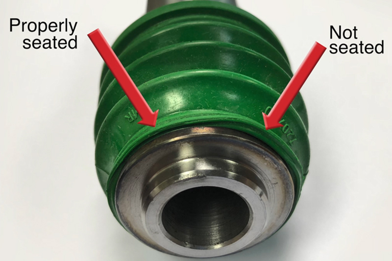
Ensure the seal is correctly located in the groove on the guide sleeve (Fig.6).
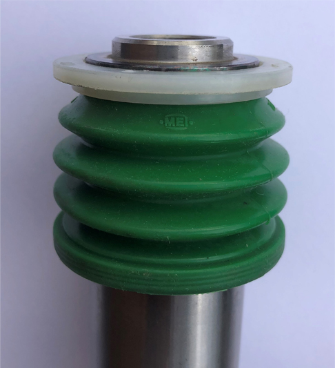
Ensure the white plastic ring is fitted correctly. This keeps the seal in the groove. See Fig.7.
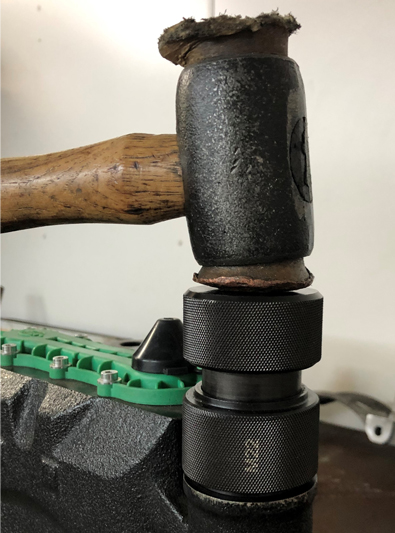
Secure the carrier in the vice and tighten the guide sleeve bolts to 180Nm, plus 90°. The guide sleeve seal must be compressed prior to cap fitment, which happens naturally if held as shown in Fig.8. If it is not compressed, the seal can balloon when the caliper is pushed back for pad fitment and become trapped. The end cap must go in exactly square – using the MEI tool kit makes this job a lot easier – if not there is a chance of damaging the cap, or even water ingress (Fig.9).
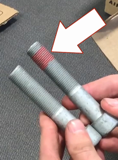
Ensure that the long bolt (with lock patch) is used for the long guide sleeve on all calipers (Fig.10).
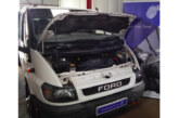
Before refitting the caliper, check the pads and rotor for damage. Now is the time to change them if there is any doubt. After refitting the caliper, check it is sliding smoothly on the guide sleeves before pad fitment. If the old caliper had seized due to water ingress, there is a chance that the water came from damaged air chamber seals. Therefore, it is crucial to check for tell-tale signs of water ingress. If it all checks out, then tighten the air chamber nuts to a snug torque, fully tightening to 180-210Nm.
Set the running clearance (0.6-1.2mm) as follows: Turn the adjuster shaft clockwise until pads touch the disc and resistance is felt (do not exceed 25Nm torque). Next, turn the adjuster shaft anti- clockwise by three clicks (note that each click corresponds to 0.6mm running clearance) to give 1.8mm clearance. This is more than required but allows the adjuster to settle to its natural position. Pump the brake pedal >5 times and the adjuster shaft will be seen to index clockwise, bringing the clearance into specified limits. Finally, check for free running of the disc, fit the adjuster cap and the job is done.