If you’re servicing light commercial vehicles, there’s every chance that you’re seeing a large volume of common rail injectors. After all, more than 95% of the LCV parc is diesel. This is a great opportunity for workshops equipped with the right tools and know-how to offer fast and accurate injector servicing.
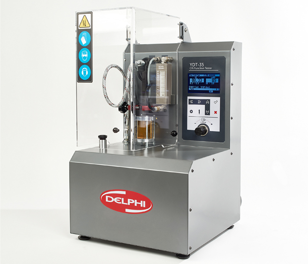
Designed by Hartridge for garages and entry-level workshops, Delphi’s YDT-35 provides this servicing capability. Complementing Delphi’s on-vehicle test solutions for common rail injectors, shown in CVW July/August, the compact tool enables technicians to troubleshoot faulty common rail injectors quickly and effectively. It combines an electrical injector test with visual spray pattern checks, to identify individual injectors that have failed – all in less than five minutes. Here are six steps to using the YDT-35:
1. Setup is simple. First secure the machine on a work bench. Then fill with calibration fluid to ISO 4113 standard, Delphi Part number HAD400, until the level is visible in the sight glass. Also fill the injector spray chamber until no air is present. Finally, connect to a 5-10bar air supply and a standard mains supply.
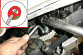
2. Cleanliness is paramount. Before fitting the injector, ensure the nozzle is free from contaminants. Use either an ultrasonic rinse tank, or soft wire brush, but remember to avoid the very tip of the injector.
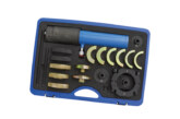
3. To mount the injector, lift the protective door and place the injector in the universal mount. Line up the spray chamber and tighten both the injector and chamber in place. Once secure, fit the flexible high pressure pipe and torque correctly to 35Nm. To complete setup, connect the back-leak pipe and electrical supply to the injector. Different adaptors are supplied to suit various applications.
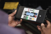
4. You are now ready to test the injector. To begin, press the start button and select the correct injector. Note the test will not begin if the wrong injector type is selected. Press start and the machine will perform an electrical test on the injector. The results and limits are displayed on screen, clearly showing pass or fail.
5. If the injector has failed the electrical test, it cannot be repaired and must be replaced. If it has passed, press stop and progress to the spray pattern check. At this point, the injector test will be activated. Set the pressure to 600-700bar and allow the injector to run for one minute to ensure the air is purged from the back-leak unit. Then perform a visual check on the spray pattern inside the spray chamber – look for consistent delivery from each nozzle hole. Allow this test to run for 30-60 seconds and record the back-leak measurement displayed on the return flow unit. Repeat this step across all four test plans for all injectors.
6. Once you have all the results, you can compare the data and quickly and easily identify which injector needs to be repaired or replaced.
What’s next – new, reman or repair?
Once you’ve identified a faulty injector, Delphi offers three service options: new, reman and repair. The new and remanufactured injectors are produced in Delphi facilities to precise OE standards, and the repair option, through its authorised Delphi Diesel Centre network. All three options use original Delphi components and adhere to manufacturer standards.
Why is injector coding important?
Whichever option you choose, the characteristics of the replacement injector will be significantly different to the part previously fitted to the vehicle. It is therefore critical that a new code is allocated to reflect the performance of the new injector. The ECU must then be re- programmed with this code when the injector is fitted to the vehicle using an EOBD diagnostic tool, such as Delphi’s DS150E. This will ensure that adjustments
to pulse times are made and that the correct fuel delivery is maintained. Failure to do this will mean that the ECU will continue to work with the previous injector’s characteristics, leading to issues such as reduced power, excessive smoke and increased engine noise.
Delphi coding explained
Delphi’s correction codes are generated by measuring the flow rate of each injector at five different pressures for C2i (230, 400, 800, 1200bar and maximum pressure) and three different pressures for C3i (400, 800bar and maximum pressure). These measurements are then compared against a target (average) injector performance to assess what pulse time adjustment is required in order to obtain the required fuel delivery. This adjustment is translated into the code.