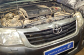
Joshua Jones, a Devon-based Garage Manager, explains how he approached a particularly puzzling diagnostics case, involving a 2005 VW Transporter T5 1.9.
The VW Transporter came in with the fairly simple complaint of an inoperative fuel gauge, but checking the instrument panel functions turned out to be quite interesting. I was advised by the driver that the fuel level readout could sometimes be accurate, but most of the time the needle would either sit close to the top or at the very bottom of the gauge.
Luckily, when I got hold of the van the gauge was showing empty despite the tank being filled recently, so I had a current symptom to follow. I began proceedings with my scan tool and checked the instrument cluster for DTCs, of which none were stored. A function self-test was available for the complete cluster so I initiated this, during which I was shown that the fuel level gauge was capable of physically operating.
The wiring diagram for the system showed that the instrument pack carried the reference voltage to the level sensor. It also showed that the ground path returned back to the clocks, this ground being shared with several other warning functions, including the park brake warning lamp. This made it quite easy to confirm that this ground path was fine in terms of the instrument panel, at least.

I wanted to confirm which end of the vehicle the problem lay at, as the pump module had no access panel. I did not want to remove the tank if I didn’t have to, especially with a fresh splash of fuel on board. Although the function test had confirmed that the gauge could operate on demand, this did not confirm that the reference signal from the clocks was intact. I removed the instrument panel to confirm that all was as it should be.
The wiring diagram detailed the pin designations for the ref output and return, which were very easy to access. When using a DVOM to check the output voltage, I initially thought that I had isolated the issue. With key on, I observed a steady 0.3V at the terminal with the circuit intact. I wrongly assumed that the ref voltage would be a solid output as opposed to a PWM, so I thought I was looking at a lack of ref output from the clocks, as long as it wasn’t being pulled low by a short circuit, of course.
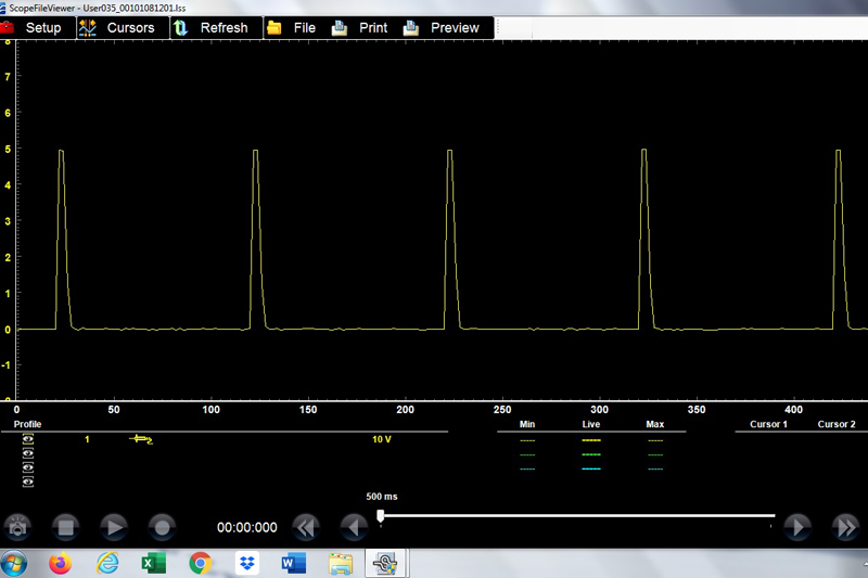
I was glad that I double checked using my scope: Fig. 1 shows a good ref signal from the clocks. The DVOM shows 0.3V, as it is around the average value of the modulated signal. If I had not observed the waveform, I would have wrongly identified the clocks as the issue. Another piece of information that I took from the scope pattern is that the peak output of the signal sits at exactly 5V, meaning that the circuit from that recorded point must be open at some point, as the peak output would be altered by the operational sender unit.
I gained access to the tank module harness at the floor of the van quite easily. I was able to check the integrity of the ref signal and the return ground (still the same colours at this point) to confirm all was well inside the vehicle. This meant that tank removal was necessary, because I now knew this is where the fault lay. The fault was visually identifiable upon the tank being lowered, with the female pin splay occurring at the pump unit multiplug. This was an easy repair, but mistakes could have easily been made if the 0.3V output had been taken at face value.